Operator’s Guide
xi
Figures
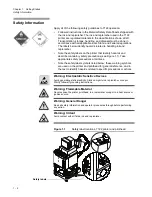
Figure 1.1
Safety label locations, 7122 printer and printhead...................... 1-2
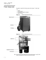
Figure 1.2
Printer components (front view).................................................. 1-4
Figure 1.3
Printer components (rear view)................................................... 1-4
Figure 1.4
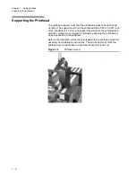
Printhead mount ......................................................................... 1-6
Figure 1.5
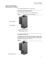
Substrate movement (7122 printhead) ....................................... 1-7
Figure 1.6
Print array ................................................................................... 1-7
Figure 1.7
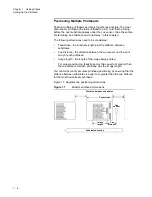
Multiple printhead dimensions .................................................... 1-8
Figure 1.8
Tach encoder.............................................................................. 1-9
Figure 1.9
Cue sensor example................................................................... 1-9
Figure 1.10
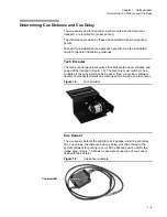
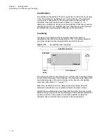
Cue distance and cue delay ..................................................... 1 -10
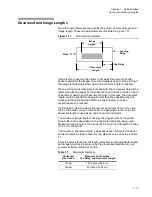
Figure 1.11
Document parameters .............................................................. 1 -11
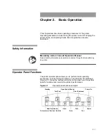
Figure 2.1
Operator panel buttons and lights............................................... 2-1
Figure 2.2
Printer - rear view ....................................................................... 2-6
Figure 3.1
Good test pattern ........................................................................ 3-3
Figure 3.2
Seal, removed 7122 printhead eyelid ......................................... 3-4
Figure 3.3
Slight raggedness, sample test pattern ..................................... 3-5
Figure 3.4
Buildup-caused missing print, sample test pattern ..................... 3-6
Figure 3.5
Crooked jets, sample test image and test pattern ...................... 3-8
Figure 3.6
Slight streaker, sample test pattern ............................................ 3-9
Figure 3.7
Open, sample test pattern .......................................................... 3-9
Figure 3.8
Slight dark defect, sample test pattern ..................................... 3 -10
Figure 3.9
Slight pickout, sample test pattern ........................................... 3 -10
Figure 3.10
Phase defect, sample test patterns .......................................... 3 -11
Figure 3.11
Compressed test image, 120 ppi .............................................. 3 -11
Figure 3.12
Elongated and truncated test image, 480 ppi ........................... 3 -12
Figure 4.1
Removing the air filter................................................................. 4-3
Figure 4.2
Bottom cover, printhead.............................................................. 4-5
Figure 4.3
Catch pan 0192385 for the 7122 printhead ................................ 4-6
Figure 4.4
Catch pan installed, 7122 printhead ........................................... 4-7
Figure 4.5
Standby pan (0194687) with grounding wire .............................. 4-7
Figure 4.6
Standby pan installed under 7122 printhead .............................. 4-8
Figure 4.7
Jet curtain, printhead running replenisher .................................. 4-9
Figure 4.8
Swabbing the 7122 printhead ..................................................... 4-9
Figure 4.9
Eyelid edge, eyelid removing for cleaning ................................ 4 -11
Содержание VERSAMARK DP7122
Страница 1: ...Kodak Versamark Inc KODAK VERSAMARK DP7122Printer Operator s Guide ...
Страница 2: ......
Страница 3: ...KODAK VERSAMARK DP7122 Printer Operator s Guide Block 3 Mod 11 ...
Страница 8: ......
Страница 24: ......
Страница 37: ...3 7 Chapter 3 Troubleshooting Identifying Print Defects Figure 3 4 continued ...
Страница 44: ......
Страница 56: ......
Страница 61: ......
Страница 62: ...0114130 602 0114130 603 Kodak Versamark Inc ...


