15
Unpacking and setup
AZURA® Valve Unifier VU 4.1 Instructions V6855
Process
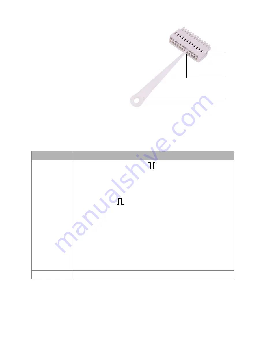
1. Insert the operating tool
3
into
an upper small opening on the
front of the terminal strip
1
.
2. Lead the cable into the opening
2
below the inserted operating
tool.
3. Remove the operating tool.
Next steps
Check if the cables are firmly
attached. Push the terminal strip
onto the multi-pin connector. Finish
the installation. Put the device into operation.
Manual control
Prerequisites
The control of the valve drive is set to input (manual control).
Signal
Explanation
EVENT/OUT
OC: TTL compatible output
passive 5 V (default with external Pull-Up up to 24 V/
25 mA)
active 0 V
TTL: TTL output
passive 0 V
active 5 V
Impulse:
0 V for min. 1000 ms
Trigger signal: 2 position valve to position 2
multi position valve to position 1
No trigger signal: 2 position valve to position 1
multi position valve not to position 1
GND
Reference point of the voltage at the signal inputs
2
3
1


