


TR850 Service Manual
(U5) and provide it for the analog power of CODEC (U30).
3.3.3. Audio Processing
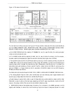
Figure 3-11 Audio Processing Schematic Diagra
As the Figure 3-11 shows, the audio processing module mainly achieves encoding and decoding with
ADC and DAC of the audio signal, including air audio forwarding and local audio TRx.
Air Audio Forwarding
The digital IF signal from the RF receiver will be first sent to the FPGA(U14) for time slot processing and
achieving the framing, filtering and extracting of the data to realize the calculation and synchronization of
the frame number; the signal will be send to the DSP of CPU (U4)via the McBSP interface for 4FSK
decoding, digital audio signal decoding and etc.. Meanwhile, the internal DSP will send the digital audio
signal which achieves the decoding and encoding to the FPGA(U14) for time slot processing and finishing
the framing, filtering and interpolation and other synchronization calculation of the data, and the digital
audio signal will then be sent to the DAC (U24) via the SPI interface for the audio digital/analog switch,
generating the analog speech two point modulation signal before being sent to the transmitter for the
audio forwarding.
Local Audio TRx
The internal DSP in the main processor(U4) connects to the CODEC(U30) via the I2S digital audio
interface. The CODEC(U30) will convert the analog audio input from the external to digital audio, then
14
Содержание TR850
Страница 1: ......
Страница 45: ...TR850 Service Manual 5 4 Connection 1 2 3 4 6 8 7 5 9 10 13 14 15 16 18 17 11 12 41 ...
Страница 90: ...TR850 Service Manual Figure 1 Rx Module Top Board PCB View 86 ...
Страница 91: ...TR850 Service Manual Figure 2 Rx Module Bottom Board PCB View 87 ...
Страница 93: ...TR850 Service Manual Figure 5 Power Amplifier Module Bottom Board PCB View 89 ...
Страница 94: ...TR850 Service Manual Figure 6 Baseband Mainboard Top Board PCB View 90 ...
Страница 95: ...TR850 Service Manual Figure 7 Baseband Mainboard Bottom Board PCB View 91 ...
Страница 96: ...TR850 Service Manual Figure 8 Front Panel Top Board PCB View Figure 9 Front Panel Bottom Board PCB View 92 ...
Страница 97: ...TR850 Service Manual Figure 10 Power Board Top Board PCB View 93 ...
Страница 114: ...TR850 Service Manual Figure 16 Baseband Mainbaord Schematic Diagram 110 ...
Страница 169: ...TR850 Service Manual Figure 1 Rx module Top Board Position Mark Diagram 165 ...
Страница 170: ...TR850 Service Manual Figure 2 Rx Module Buttom Board Position Mark Diagram 166 ...
Страница 172: ...TR850 Service Manual Figure 5 Power Amplifier Module Buttom Position Mark Diagram 168 ...
Страница 173: ...TR850 Service Manual Figure 6 Baseband Mainboard Top Board Position Mark Diagram 169 ...
Страница 174: ...TR850 Service Manual Figure 7 Baseband Mainboard Buttom Board Position Mark Diagram 170 ...
Страница 176: ...TR850 Service Manual Figure 10 Power Board Top Board Position Mark Diagram 172 ...
Страница 193: ...TR850 Service Manual Figure 16 Baseband Mainboard Schematic Diagram 189 ...