


TR850 Service Manual
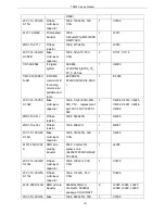
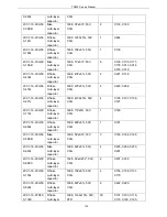
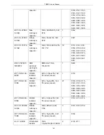
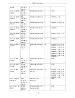
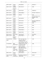
Table 2 Part List(TX Module Section)
Part No.
Part Name
Specification
Quantity
Location
3FW1-42932-30
2320
R SMD fuse
429003/433003/466003,
3216,3A/32V
1
CB400
1DR1-MM3Z12V
T1G
Anti-static
zener diode
MM3Z12VT1G, 3V,
SOD323, pb-free
1
D400
1DS1-HSC277
R SMD
switchdiode(of
f production)
HSC277,1608
1
D100
1DV1-1SV278
R SMD
varactor diode
1SV278(T1)
2
D105,D110
1DV1-1SV305
R SMD
varactor diode
1SV305
8
D101,D102,D103,D104,
D106,D107,D108,D109
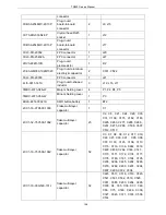
1IS1-LM2941S
SMD
specialized IC
LM2941S/TO-236, 5PIN,
low dropout voltage
regulator, pb-free
1
U400
1IS1-SKY72310
PLL chip
SKY72310,24 pin QFN
4mmX4mm
pb-free(QFN-N24_B4x4-
P0_5), pb-free
1
IC100
1IS1-PGA103
Broad band
low noise
amplifier
PGA-103+,0.05to4GHz,
SOT-89,PACKAGE,Mini-
Circuits brand,RoHS
1
IC306
1IS1-TC75S51F
SMD single
operational
amplifier IC
TC75S51F,SSOP5-P-0.9
5
2
IC300,IC301
1IS1-XC6209F30
2PR
SMD voltage
regulator IC
XC6209F302PR,
SOT-89-5, 3.0V
1
IC101
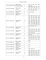
1IS1-XC6209F33
2PR
SMD voltage
regulator IC
XC6209F332PR,
SOT-89-5, 3.3V
1
IC103
1IS1-XC6209F50
2PR
SMD voltage
regulator IC
XC6209F502PR,
SOT-89-5, 5.0V
4
IC102,IC104,IC105,IC30
2
1TC1-UMC4
R SMD
multiunit tube
UMC4,NPN/PNP
multiunit tube
1
U100
1TF1-2SJ243
R SMD
FET(off
production)
2SJ243-SMD
1
Q104
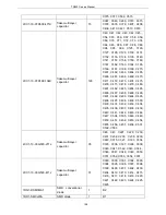
1TT1-2SC3356-
R24
R SMD triode
(off
production)
2SC3356-R24,SOT23,N
PN
3
Q105,Q106,Q202
1TT1-2SC4617-
R
R SMD triode
2SC4617-R(BR),EMT3
1
Q101
1TT1-DTC114YE SMD triode
Digital triode
2
Q204,Q400
145
Содержание TR850
Страница 1: ......
Страница 45: ...TR850 Service Manual 5 4 Connection 1 2 3 4 6 8 7 5 9 10 13 14 15 16 18 17 11 12 41 ...
Страница 90: ...TR850 Service Manual Figure 1 Rx Module Top Board PCB View 86 ...
Страница 91: ...TR850 Service Manual Figure 2 Rx Module Bottom Board PCB View 87 ...
Страница 93: ...TR850 Service Manual Figure 5 Power Amplifier Module Bottom Board PCB View 89 ...
Страница 94: ...TR850 Service Manual Figure 6 Baseband Mainboard Top Board PCB View 90 ...
Страница 95: ...TR850 Service Manual Figure 7 Baseband Mainboard Bottom Board PCB View 91 ...
Страница 96: ...TR850 Service Manual Figure 8 Front Panel Top Board PCB View Figure 9 Front Panel Bottom Board PCB View 92 ...
Страница 97: ...TR850 Service Manual Figure 10 Power Board Top Board PCB View 93 ...
Страница 114: ...TR850 Service Manual Figure 16 Baseband Mainbaord Schematic Diagram 110 ...
Страница 169: ...TR850 Service Manual Figure 1 Rx module Top Board Position Mark Diagram 165 ...
Страница 170: ...TR850 Service Manual Figure 2 Rx Module Buttom Board Position Mark Diagram 166 ...
Страница 172: ...TR850 Service Manual Figure 5 Power Amplifier Module Buttom Position Mark Diagram 168 ...
Страница 173: ...TR850 Service Manual Figure 6 Baseband Mainboard Top Board Position Mark Diagram 169 ...
Страница 174: ...TR850 Service Manual Figure 7 Baseband Mainboard Buttom Board Position Mark Diagram 170 ...
Страница 176: ...TR850 Service Manual Figure 10 Power Board Top Board Position Mark Diagram 172 ...
Страница 193: ...TR850 Service Manual Figure 16 Baseband Mainboard Schematic Diagram 189 ...


