


TR850 Service Manual
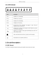
2.2. LED Indicator
LED
Description
TX-A
Indicates slot 1 is transmitting.
RX-A
Indicates slot 1 is receiving.
TX-B
Indicates slot 2 is transmitting.
RX-B
Indicates slot 2 is receiving.
Repeater mode. When illuminated, the repeater is active. When the
repeater is inactive, the LED is off.
Analog mode. For analog or mixed signals the LED flashes when active.
The LED is off when inactive.
Digital mode. For digital or mixed signals the LED flashes when active. The
LED is off when inactive.
Alarm mode. Illuminates when there is a problem with the repeater.
Illuminates when the repeater is switched on.
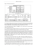
3. Circuit Description
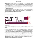
3.1. RF Circuit
The RF part is composed of transmitter module, power amplifier module and receiver module.
3
Содержание TR850
Страница 1: ......
Страница 45: ...TR850 Service Manual 5 4 Connection 1 2 3 4 6 8 7 5 9 10 13 14 15 16 18 17 11 12 41 ...
Страница 90: ...TR850 Service Manual Figure 1 Rx Module Top Board PCB View 86 ...
Страница 91: ...TR850 Service Manual Figure 2 Rx Module Bottom Board PCB View 87 ...
Страница 93: ...TR850 Service Manual Figure 5 Power Amplifier Module Bottom Board PCB View 89 ...
Страница 94: ...TR850 Service Manual Figure 6 Baseband Mainboard Top Board PCB View 90 ...
Страница 95: ...TR850 Service Manual Figure 7 Baseband Mainboard Bottom Board PCB View 91 ...
Страница 96: ...TR850 Service Manual Figure 8 Front Panel Top Board PCB View Figure 9 Front Panel Bottom Board PCB View 92 ...
Страница 97: ...TR850 Service Manual Figure 10 Power Board Top Board PCB View 93 ...
Страница 114: ...TR850 Service Manual Figure 16 Baseband Mainbaord Schematic Diagram 110 ...
Страница 169: ...TR850 Service Manual Figure 1 Rx module Top Board Position Mark Diagram 165 ...
Страница 170: ...TR850 Service Manual Figure 2 Rx Module Buttom Board Position Mark Diagram 166 ...
Страница 172: ...TR850 Service Manual Figure 5 Power Amplifier Module Buttom Position Mark Diagram 168 ...
Страница 173: ...TR850 Service Manual Figure 6 Baseband Mainboard Top Board Position Mark Diagram 169 ...
Страница 174: ...TR850 Service Manual Figure 7 Baseband Mainboard Buttom Board Position Mark Diagram 170 ...
Страница 176: ...TR850 Service Manual Figure 10 Power Board Top Board Position Mark Diagram 172 ...
Страница 193: ...TR850 Service Manual Figure 16 Baseband Mainboard Schematic Diagram 189 ...


