


TR850 Service Manual
2RS1-16-124J
R Flake
resistor
1608, 120K±5%
2
R339, R341
2RS1-16-220J
R Flake
resistor
1608,
22Ω±5%
1
R218
2RS1-16-221J
R Flake
resistor
1608,
220Ω±5%
2
R211, R212
2RS1-16-270J
R Flake
resistor
1608,
27Ω±5%
1
R209
2RS1-16-302J
Flake resistor
1608, 3K±5%
2
R104, R116
2RS1-16-472J
R Flake
resistor
1608, 4.7K±5%
2
R101, R109
2RS1-16-473J
R Flake
resistor
1608, 47K±5%
5
R110,
R220,
R345,
R400, R401
2RS1-16-511J
Flake resistor
1608,
510Ω±5%
1
R219
2RS1-16-563J
R Flake
resistor
1608, 56K±5%
1
R207
2RS1-16-682J
R Flake
resistor
1608, 6.8K±5%
2
R102, R112
2RS1-20-000O
R Flake
resistor
2012,
0Ω
2
L212, L213
5FE1-BLM11A60
1S
R patch EMI
suppression
filter
1608,
BLM11A601S/BLM18AG
601S(0138-05)
28
L100, L101, L102, L108,
L109, L110, L112, L114,
L121, L123, L202, L207,
L300, R301, L301, R302,
R303,
R304,
R305,
R306,
R307,
R308,
R309,
R310,
R311,
R312, R329, R351
5FE1-BLM21P30
0S
R patch EMI
suppression
filter
2012,
BLM21P300S/BLM21PG
300S(0149-05)
1
L400
5FQ1-LFCN-400
Low pass filter
LFCN-400, 8.5W, DC to
400MHz, FV120,
Mini-Circuits
1
U402
5OT1-12R8-CEC
3-0503
R patch
temperature
compensated
crystal
oscillator
NT5032SA/NT5032SC,
12.8MHz±2.5PPm,
5.0*3.2*1.6mm
1
X100
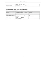
6PM7-4067-HTB
DR650-02Tx
board
DR650-DVC0-TXBORA
D-20130319.PCB,
1.6MM thick, FR-4,
70X194M, 4 layers
1
2RE1-16-2200
Patch
precision
resistor
1608,
220Ω±1%
1
R126
71
Содержание TR850
Страница 1: ......
Страница 45: ...TR850 Service Manual 5 4 Connection 1 2 3 4 6 8 7 5 9 10 13 14 15 16 18 17 11 12 41 ...
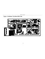
Страница 90: ...TR850 Service Manual Figure 1 Rx Module Top Board PCB View 86 ...
Страница 91: ...TR850 Service Manual Figure 2 Rx Module Bottom Board PCB View 87 ...
Страница 93: ...TR850 Service Manual Figure 5 Power Amplifier Module Bottom Board PCB View 89 ...
Страница 94: ...TR850 Service Manual Figure 6 Baseband Mainboard Top Board PCB View 90 ...
Страница 95: ...TR850 Service Manual Figure 7 Baseband Mainboard Bottom Board PCB View 91 ...
Страница 96: ...TR850 Service Manual Figure 8 Front Panel Top Board PCB View Figure 9 Front Panel Bottom Board PCB View 92 ...
Страница 97: ...TR850 Service Manual Figure 10 Power Board Top Board PCB View 93 ...
Страница 114: ...TR850 Service Manual Figure 16 Baseband Mainbaord Schematic Diagram 110 ...
Страница 169: ...TR850 Service Manual Figure 1 Rx module Top Board Position Mark Diagram 165 ...
Страница 170: ...TR850 Service Manual Figure 2 Rx Module Buttom Board Position Mark Diagram 166 ...
Страница 172: ...TR850 Service Manual Figure 5 Power Amplifier Module Buttom Position Mark Diagram 168 ...
Страница 173: ...TR850 Service Manual Figure 6 Baseband Mainboard Top Board Position Mark Diagram 169 ...
Страница 174: ...TR850 Service Manual Figure 7 Baseband Mainboard Buttom Board Position Mark Diagram 170 ...
Страница 176: ...TR850 Service Manual Figure 10 Power Board Top Board Position Mark Diagram 172 ...
Страница 193: ...TR850 Service Manual Figure 16 Baseband Mainboard Schematic Diagram 189 ...


