


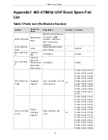


TR850 Service Manual
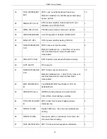
3WPT-P26350PH25410P
With dual-plugged flat cable, AWG26#, 2.54 interval,
double flat cable, wire length 350mm, 10P socket.
1
—
12
3WPT-P26080PH25410P
With dual-plugged flat cable, AWG26#, 2.54
interval, double flat cable, wire length 80mm, 10P
socket, double-headed socket.
17
—
33
3WPD-160140-1PIN
Connected to ground wire 1Pin, blue wire, 140mm
length,wire size,:16AWG.; two ends with round
terminal
31(ground
terminal)
—
machine case
Fan wire
Come with fan
11
—
32
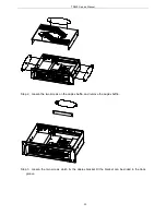
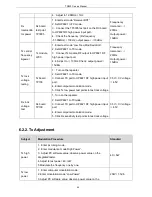
6. Adjustment
During maintenance, the repeater may needs some testing and modulation for technical index after
changing the components.
6.1. Preparation
Please prepare the tools and equipment before testing the DMR repeater:
Integrated tester
PC and CPSp software
AEROFLEX 3920
Spectrum analyzer FSU
Antenna interface converter
Universal interface
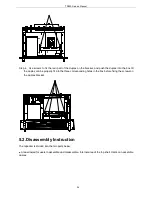
6.2. Method of Modulation and Test
6.2.1. Local Oscillator Adjustment
Subject
Test Point
Test Procedure
Standard
12.8M
Clock
base band
board J6
1. Enter test mode “12.8M Clock”.
2. Set HP8921 to TX mode; connect the reference
frequency port to HP8921 RF high power input
port.
3. Enter computer modulation mode.
≤±
1Hz
44
Содержание TR850
Страница 1: ......
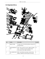
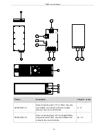
Страница 45: ...TR850 Service Manual 5 4 Connection 1 2 3 4 6 8 7 5 9 10 13 14 15 16 18 17 11 12 41 ...
Страница 90: ...TR850 Service Manual Figure 1 Rx Module Top Board PCB View 86 ...
Страница 91: ...TR850 Service Manual Figure 2 Rx Module Bottom Board PCB View 87 ...
Страница 93: ...TR850 Service Manual Figure 5 Power Amplifier Module Bottom Board PCB View 89 ...
Страница 94: ...TR850 Service Manual Figure 6 Baseband Mainboard Top Board PCB View 90 ...
Страница 95: ...TR850 Service Manual Figure 7 Baseband Mainboard Bottom Board PCB View 91 ...
Страница 96: ...TR850 Service Manual Figure 8 Front Panel Top Board PCB View Figure 9 Front Panel Bottom Board PCB View 92 ...
Страница 97: ...TR850 Service Manual Figure 10 Power Board Top Board PCB View 93 ...
Страница 114: ...TR850 Service Manual Figure 16 Baseband Mainbaord Schematic Diagram 110 ...
Страница 169: ...TR850 Service Manual Figure 1 Rx module Top Board Position Mark Diagram 165 ...
Страница 170: ...TR850 Service Manual Figure 2 Rx Module Buttom Board Position Mark Diagram 166 ...
Страница 172: ...TR850 Service Manual Figure 5 Power Amplifier Module Buttom Position Mark Diagram 168 ...
Страница 173: ...TR850 Service Manual Figure 6 Baseband Mainboard Top Board Position Mark Diagram 169 ...
Страница 174: ...TR850 Service Manual Figure 7 Baseband Mainboard Buttom Board Position Mark Diagram 170 ...
Страница 176: ...TR850 Service Manual Figure 10 Power Board Top Board Position Mark Diagram 172 ...
Страница 193: ...TR850 Service Manual Figure 16 Baseband Mainboard Schematic Diagram 189 ...