


TR850 Service Manual
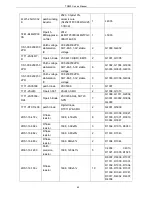
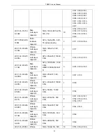
resistor
2RS1-16-821J
R Flake
resistor
1608,
820Ω±5%
1
R131
2RS1-16-510J
R Flake
resistor
1608,
51Ω±5%
1
R134
2RS1-16-512J
Flake resistor
1608, 5.1K±5%
3
R137, R138, R135
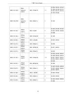
2RE1-16-1000
patch
precision
resistor
1608,
100Ω±1%
1
R142
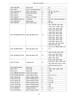
1IS1-XC6701D3
32PR
3.3VLDO
28V high input voltage,
fast speed and low
consumption LDO with
fast speed and low
consumption, 3.3V
output, SOT-89
1
U102
1IS1-LM2941S
Patch
specialized IC
LM2941S/TO-236, 5PIN,
low dropout voltage
regulator, pb-free
1
U200
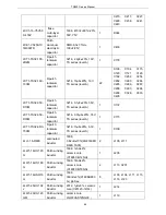
6PM7-4071-HPA
SEPURA
power
amplification
board PCB
power amplification
board PCB, four layers,
FR4, 58.24X70,
RFAMPLIFIER-2013071
9.PCB, pb-free
1
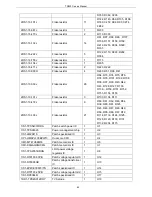
2CC1-32-C0G50
1-1R0C
Flake
multi-layer
capacitor
3216, 1P±0.25%, 500V,
C0G,
GRM31M5C2H1R0CY2
1B
1
C119
1DR1-XBS053V
15R-1G
Patch
schottky diode
XBS053V15R-1G,
SOD-523, VR=20V,
VF=0.40V, manufatured
by TOREX, pb-free
1
D201
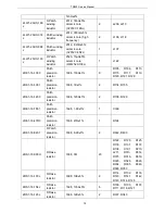
2CC1-32-C0G50
0-102J
Flake
multi-layer
capacitor
3216, 1000P±5%, 50V,
C0G
1
L113
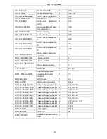
Table4 Parts List (Baseband Mainboard)
Part No.
Acccessory Names
Quantity
Location
3CB3-VH3096-2P
DC power socket
1
J1
3CB3-S6160BK1
Board-to-board connector
2
J2
3CR7-SMA-50KE
RF coaxial connectorw
3
J6, J7, J8
3CB3-A2548WV-2X05P
Board-to-board connector
4
J5, J18, J19, J23
3CB3-A2548WV-2X13P
Board-to-board connector
2
J9, J15
76
Содержание TR850
Страница 1: ......
Страница 45: ...TR850 Service Manual 5 4 Connection 1 2 3 4 6 8 7 5 9 10 13 14 15 16 18 17 11 12 41 ...
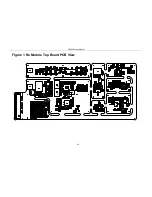
Страница 90: ...TR850 Service Manual Figure 1 Rx Module Top Board PCB View 86 ...
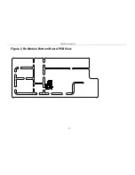
Страница 91: ...TR850 Service Manual Figure 2 Rx Module Bottom Board PCB View 87 ...
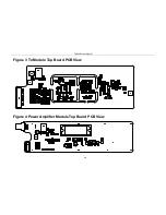
Страница 93: ...TR850 Service Manual Figure 5 Power Amplifier Module Bottom Board PCB View 89 ...
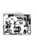
Страница 94: ...TR850 Service Manual Figure 6 Baseband Mainboard Top Board PCB View 90 ...
Страница 95: ...TR850 Service Manual Figure 7 Baseband Mainboard Bottom Board PCB View 91 ...
Страница 96: ...TR850 Service Manual Figure 8 Front Panel Top Board PCB View Figure 9 Front Panel Bottom Board PCB View 92 ...
Страница 97: ...TR850 Service Manual Figure 10 Power Board Top Board PCB View 93 ...
Страница 114: ...TR850 Service Manual Figure 16 Baseband Mainbaord Schematic Diagram 110 ...
Страница 169: ...TR850 Service Manual Figure 1 Rx module Top Board Position Mark Diagram 165 ...
Страница 170: ...TR850 Service Manual Figure 2 Rx Module Buttom Board Position Mark Diagram 166 ...
Страница 172: ...TR850 Service Manual Figure 5 Power Amplifier Module Buttom Position Mark Diagram 168 ...
Страница 173: ...TR850 Service Manual Figure 6 Baseband Mainboard Top Board Position Mark Diagram 169 ...
Страница 174: ...TR850 Service Manual Figure 7 Baseband Mainboard Buttom Board Position Mark Diagram 170 ...
Страница 176: ...TR850 Service Manual Figure 10 Power Board Top Board Position Mark Diagram 172 ...
Страница 193: ...TR850 Service Manual Figure 16 Baseband Mainboard Schematic Diagram 189 ...


