


TR850 Service Manual
4.2.1. Parameters setting
Parameter settings steps are as follows
Step 1. Install the right version of the CPSp user programming software.
Step 2. Using RJ45 ethernet cable to connect the repeater with Ethernet port of computer through
HUB/switchboard.
Step 3. Make sure the repeater is powered on.
Step 4. Operate CPSp user programming software for the settings of related parameters.
The user can read parameter configuration through CPSp user programming software.
4.2.2. Install CPSp user programming software
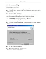
Installation steps of CPSp user programming software:
Step 1. Double click the installation file of CPSp user programming software, and the interface below will
pop up.
Step 2. Click “Next” and enter the next interface.
Step 3. (Option) Click browse and select the installation route.
This step can be skipped if using the default route.
29
Содержание TR850
Страница 1: ......
Страница 45: ...TR850 Service Manual 5 4 Connection 1 2 3 4 6 8 7 5 9 10 13 14 15 16 18 17 11 12 41 ...
Страница 90: ...TR850 Service Manual Figure 1 Rx Module Top Board PCB View 86 ...
Страница 91: ...TR850 Service Manual Figure 2 Rx Module Bottom Board PCB View 87 ...
Страница 93: ...TR850 Service Manual Figure 5 Power Amplifier Module Bottom Board PCB View 89 ...
Страница 94: ...TR850 Service Manual Figure 6 Baseband Mainboard Top Board PCB View 90 ...
Страница 95: ...TR850 Service Manual Figure 7 Baseband Mainboard Bottom Board PCB View 91 ...
Страница 96: ...TR850 Service Manual Figure 8 Front Panel Top Board PCB View Figure 9 Front Panel Bottom Board PCB View 92 ...
Страница 97: ...TR850 Service Manual Figure 10 Power Board Top Board PCB View 93 ...
Страница 114: ...TR850 Service Manual Figure 16 Baseband Mainbaord Schematic Diagram 110 ...
Страница 169: ...TR850 Service Manual Figure 1 Rx module Top Board Position Mark Diagram 165 ...
Страница 170: ...TR850 Service Manual Figure 2 Rx Module Buttom Board Position Mark Diagram 166 ...
Страница 172: ...TR850 Service Manual Figure 5 Power Amplifier Module Buttom Position Mark Diagram 168 ...
Страница 173: ...TR850 Service Manual Figure 6 Baseband Mainboard Top Board Position Mark Diagram 169 ...
Страница 174: ...TR850 Service Manual Figure 7 Baseband Mainboard Buttom Board Position Mark Diagram 170 ...
Страница 176: ...TR850 Service Manual Figure 10 Power Board Top Board Position Mark Diagram 172 ...
Страница 193: ...TR850 Service Manual Figure 16 Baseband Mainboard Schematic Diagram 189 ...


