


16-10-200716-10-2007
MKIV OPERATOR’S MANUAL
17
At the exit of the spectrometer is a cylindrical mask which exposes only one wavelength slit at a
time. The mask is positioned by a stepper motor which cycles through all five operating
wavelengths, approximately once per second.
Spectrometer Detailed Description
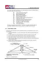
Light enters the entrance slit and passes through a tilted lens [LE 5] which corrects for the coma
and astigmatic aberrations inherent in an Ebert system. The light is collimated by a spherical
mirror onto a diffraction grating where it is dispersed. A second mirror reflection focuses the
spectrum onto the focal plane of a slotted cylindrical slit mask positioned at the exit of the
spectrometer. After wavelength selection by the slit mask, the light passes through the exit slit
plate. Six exit slits are located along the focal plane at the appropriate wavelength positions.
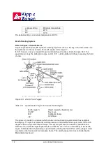
Entrance and Exit Slit Plates
The entrance slit and six exit slits [ES 1, EX 1] are etched into 0.1-mm-thick disks of hard shim
steel. One of the six exit slits (slit #0) is used for wavelength calibration against the 302-nm group
of mercury lines; the other five are for intensity measurements and are nominally set at 306.3/431.4,
310.1/437.3, 313.5/442.6, 316.8/448.1, and 320.1/453.2 nm. The dimensions for the entrance and
exit slits are listed in the Selected Parts List.
Both slit plates are positioned on their respective housings by locating pins which orient the slit axis
to within 0. 1°. Both plates are blackened to minimize light reflections.
Correction Lens
The correction lens [LE 5] has a convex-cylindrical surface (radius 170.0 mm) and a concave-
spherical surface (radius 230.0 mm).
Both surfaces are coated with a layer of magnesium fluoride to minimize reflectance at 315.0 nm
for an incidence angle of 29°. The lens is mounted in the entrance-slit housing at an angle of 29°
to
the optical axis with the concave-spherical surface facing the entrance slit. The axis of the
cylindrical surface is positioned in the horizontal plane to within 1°.
Spherical Mirror
The spherical mirror [SM 1 ] has a 324 mm radius-of-curvature. The spherical surface is ground
from a rectangular pyrex blank. The surface is polished, coated with aluminum, and then coated
with magnesium fluoride to maximize reflection at 315.0 nm.
Spring-loaded mounts secure the spherical surfaces of the mirrors against three adjustment screws
which are normal to the spherical surfaces in the horizontal plane of the spectrometers. The mirrors
are allowed to move on a spherical surface defined by the three adjustment screws, up to a limit of
0.25 mm in the horizontal and vertical. Nylon screws prevent the mirrors from moving beyond this
limit.
Diffraction Grating
The diffraction grating [GR 1 ] is a 1200 line / mm holographic plane-reflectance type, operated in
the third order in the UV for ozone measurements, and in the second order in the Blue region. The
grating has optimum efficiency over the range 225 to 450 nm in the first order.
The grating is secured with high-quality adhesive to three small blocks which provide kinematic
mounts, as well as fine adjustment for rotation of the grating about the two axes perpendicular to
the grating grooves. The three blocks are thus part of the grating and are the basis of point, slot,
and plane mounts which allows adjustment by three screws fixed in the grating-mount plates. These
plates are suspended on a set of cross-springs which constrain the gratings to rotate in the vertical
axis (the axis parallel to the grating grooves). The cross-spring suspension acts as a frictionless
bearing. Rotation of the grating is controlled by two micrometers acting at the end of lever arms
such that a 0.03 mm adjustment of the micrometers represents approximately a 0.1 nm wavelength
change at the exit-slit plane.
2. SYSTEM DESCRIPTION
Содержание BREWER MK IV
Страница 1: ...INSTRUCTION MANUAL OM BA C230 B Mk IV...
Страница 2: ...REVISION HISTORY REV DESCRIPTION DCN DATE APPD B Update 99 16 12 C Update 07 16 10...
Страница 3: ...ii...
Страница 5: ...2...
Страница 7: ...4...
Страница 25: ...MKIV OPERATOR S MANUAL 22...
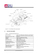
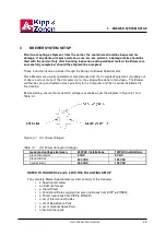
Страница 27: ...MKIV OPERATOR S MANUAL 24 Figure 3 2 Brewer Equipment Setup Figure 3 3 Brewer Spectrophotometer Tracker Tripod...
Страница 57: ...MKIV OPERATOR S MANUAL 54...
Страница 61: ...MKIV OPERATOR S MANUAL 58...
Страница 81: ...MKIV OPERATOR S MANUAL 78...
Страница 91: ...MKIV OPERATOR S MANUAL 88...
Страница 93: ...MKIV OPERATOR S MANUAL 90...
Страница 127: ...MKIV OPERATOR S MANUAL 124...
Страница 133: ...MKIV OPERATOR S MANUAL 130...
Страница 135: ...MKIV OPERATOR S MANUAL 132...


