58
Black line tracking refers to the car drives along the black line on the white floor, it can know where to
drive according to the received reflected light due to the different light reflection coefficient on the black and
white floor.
White line tracking refers to the car drives along the white line on the black floor, it can know where to
drive according to the received reflected light due to the different light reflection coefficient on the white and
black floor.
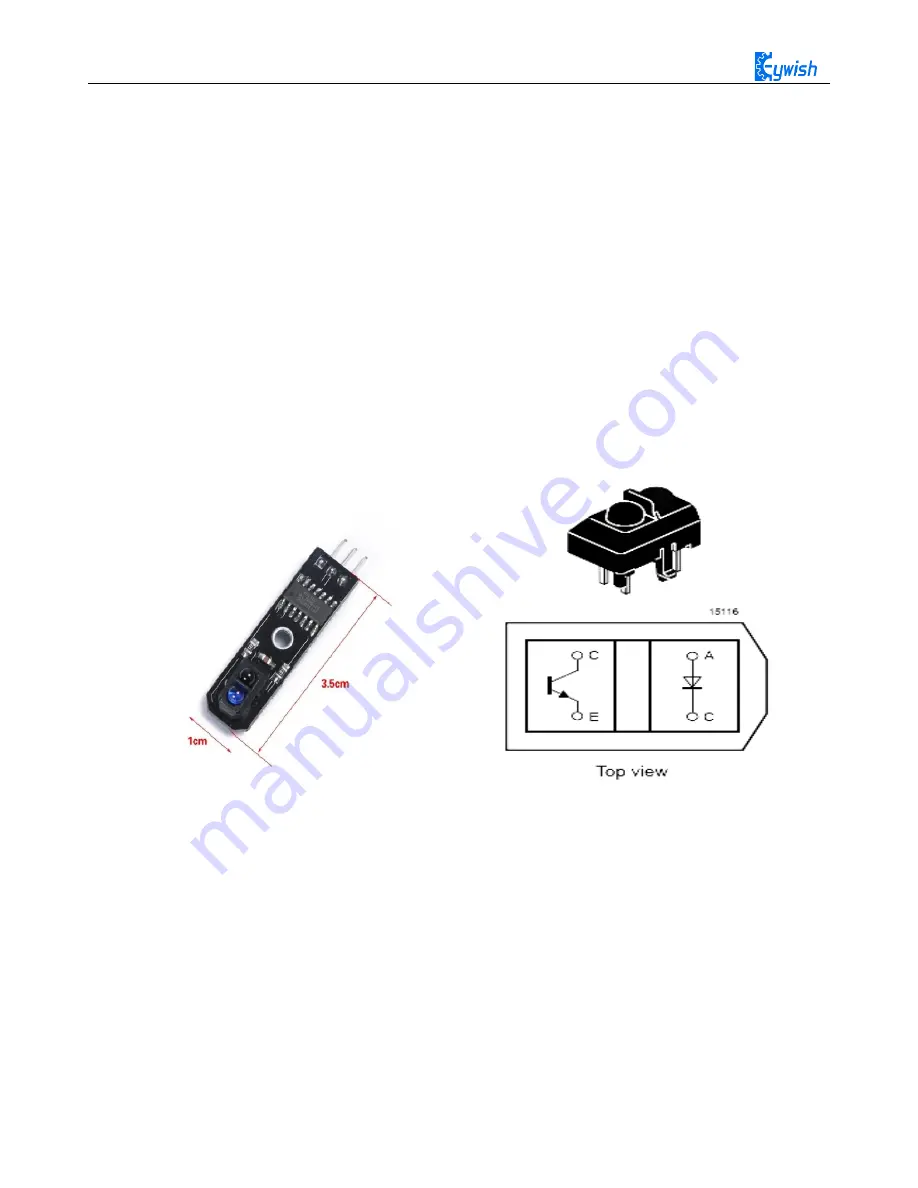
In the "Hummer-Bot" car, we use the TCRT5000 sensor as tracing module, TCRT5000 infrared reflection
sensor is a photoelectric sensor which consists of an infrared emitting diode and a NPN infrared photoelectric
transistor. The detectable reflective distance is 1mm-25mm, the sensor is specially equipped with M3 fixed
installation holes, so it is easy to adjust the direction, it also has the 74HC14 Schmidt trigger inverter which
ensure the clean signal, the good wave shape and the strong driving ability. It can be applied to robot obstacle
avoidance, robot tracing ( detecting black line in white background and detecting white line in black
background ), which is the necessary sensor for tracing line robot and other occasions. The PCB size is
3.5cm*1cm, and the physical map is shown in Fig.3.2.13.
Fig.3.2.13 Physical Map of the Module
3.2.3.2 Working Principle
In the above, we talked about two patterns of tracing-the white line and the black line. In fact, either the
black line or the white line, we usually adopt the infrared detection method.
Infrared detection method means that different objects with different colors have the different infrared
reflection characteristics. The car launches the infrared to the ground continually during driving process, the
infrared receiving tube will be in a shutdown state and the output of the module is low level when the emitted
infrared is not reflected or the reflected infrared is not strong enough, and indicating diode will be off; when
the diffuse reflection occurred on a white floor, the intense reflected infrared will be received by the receiving
tube on the car, the photosensitive triode will be saturated, the output end of the module is high level and the
indicating diode will light.
Содержание Hummer-Bot
Страница 1: ...Hummer Bot Instruction Manual Github https github com keywish keywish hummer bot...
Страница 7: ...4...
Страница 8: ...5...
Страница 9: ...6...
Страница 10: ...7...
Страница 13: ...10 Fig 2 2 Several commonly usedArduino...
Страница 15: ...12 After the completion as shown...
Страница 16: ...13 The second step is to Welding wire on the motor...
Страница 17: ...14 After the completion as shown...
Страница 19: ...16 Fig 3 1 3 Diagram of Aluminum Alloy Bracket Installation...
Страница 20: ...17 Fig 3 1 4 Diagram of Motor Installation Fig 3 1 5 Fixing Screw for Motor...
Страница 24: ...21 Fig 3 1 10 Diagram of Wheel Installation Fig 3 1 10 Diagram of Wheel Screw Fixation...
Страница 29: ...26 Fig 3 1 15 Diagram of Tracing Module Installation...
Страница 30: ...27 Fig 3 1 16 Diagram of Screw Brackets Fig 3 1 17 The Back of Complete Installation...
Страница 32: ...29 First install the screws on the UNO After the completion as shown...
Страница 33: ...30 Then install UNO on acrylic plates Fig 3 1 20 Diagram of Arduino Mainboard and Battery Box Installation...
Страница 43: ...40 Fig 3 1 33 Diagram of Wires Arrangement Fig3 1 34 the Effect of Whole Assembly...
Страница 56: ...53 Fig 3 2 11 Diagram of Data with Obstacles Fig 3 2 12 Diagram of Data without Obstacles...
Страница 69: ...66 Fig 3 2 22 Diagram of Steering Gear Fig 3 2 23 Composition of Steering Gear...
Страница 93: ...90 Fig 3 2 42 Receiving Head Position Fig 2 3 43 Installation of Receiving Head...


