98
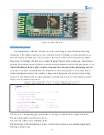
Fig.3.2.47 HC-05 Module
3.2.7.2 Bluetooth protocol
Using Bluetooth to control the car means we use the Android app to control the Bluetooth sending
instructions to the Arduino serial port, so as to control the motor's forwarding, reversing, speed and so on.
Since the wireless communication is involved, one of the essential issues is the communication problem
between the two terminals. But there is no common "language" between them, so designing communication
protocols are required to ensure a perfect interaction between Android and Arduino. The main process is: the
Android identification terminal packs the detected commands into the corresponding data packets, and then
sends them to the Bluetooth module (HC-05). When HC-05 receives the packets, it will transmit them to
Arduino through the serial port, then Arduino to analyze the data packets and execute the corresponding
actions. The data format sent by the upper computer end (Android) is as follows, which mainly contains 6
fields, we use a structure to represent it
Start_code Length
Type
Data Checksum
Tail
The start_code is the beginning part of the packet, for example, the unification is designated as 0xAA.
The type represents the type of the slave device.
The addr is the address of the controlling device.
The function means the functional types of device which need to control, we are currently supporting the
following functional types
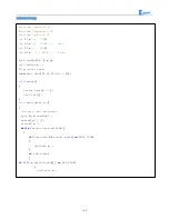
typedef
struct
{
unsigned
char
start_code
;
// 8bit 0xAA
unsigned
char
type
;
unsigned
char
addr
;
unsigned
short
int
function
;
// 16 bit
unsigned
char
*
data
;
// n bit
unsigned
short
int
sum
;
// check sum
unsigned
char
end_code
;
// 8bit 0x55
}
ST_protocol
;
Содержание Hummer-Bot
Страница 1: ...Hummer Bot Instruction Manual Github https github com keywish keywish hummer bot...
Страница 7: ...4...
Страница 8: ...5...
Страница 9: ...6...
Страница 10: ...7...
Страница 13: ...10 Fig 2 2 Several commonly usedArduino...
Страница 15: ...12 After the completion as shown...
Страница 16: ...13 The second step is to Welding wire on the motor...
Страница 17: ...14 After the completion as shown...
Страница 19: ...16 Fig 3 1 3 Diagram of Aluminum Alloy Bracket Installation...
Страница 20: ...17 Fig 3 1 4 Diagram of Motor Installation Fig 3 1 5 Fixing Screw for Motor...
Страница 24: ...21 Fig 3 1 10 Diagram of Wheel Installation Fig 3 1 10 Diagram of Wheel Screw Fixation...
Страница 29: ...26 Fig 3 1 15 Diagram of Tracing Module Installation...
Страница 30: ...27 Fig 3 1 16 Diagram of Screw Brackets Fig 3 1 17 The Back of Complete Installation...
Страница 32: ...29 First install the screws on the UNO After the completion as shown...
Страница 33: ...30 Then install UNO on acrylic plates Fig 3 1 20 Diagram of Arduino Mainboard and Battery Box Installation...
Страница 43: ...40 Fig 3 1 33 Diagram of Wires Arrangement Fig3 1 34 the Effect of Whole Assembly...
Страница 56: ...53 Fig 3 2 11 Diagram of Data with Obstacles Fig 3 2 12 Diagram of Data without Obstacles...
Страница 69: ...66 Fig 3 2 22 Diagram of Steering Gear Fig 3 2 23 Composition of Steering Gear...
Страница 93: ...90 Fig 3 2 42 Receiving Head Position Fig 2 3 43 Installation of Receiving Head...


