34
After installing the steering gear, you can add the ultrasonic module on it. In order to reduce the later
steering angle adjustment, we adjust the steering gear to 90 degrees, and copy the following program to the
compiler environment (you can also directly open the program in the CD), then connect the signal
line(Orange) on steering gear to the 13 IO port on Arduino, After the servo rotates to 90°, we can install the
servo bracket on the servo, and after the installation, we can fix it with screws., the installation is shown in
Fig.3.1.24.
#include <Servo.h>
Servo myservo
;
// create servo object to control a servo
int
pos
=
90
;
// variable to store the servo position
void
setup
()
{
myservo
.
attach
(
13
);
// attaches the servo on pin 9 to the servo object
}
void
loop
()
{
myservo
.
write
(
pos
);
// tell servo to go to position in variable 'pos'
delay
(
15
);
// waits 15ms for the servo to reach the position
}
}
Содержание Hummer-Bot
Страница 1: ...Hummer Bot Instruction Manual Github https github com keywish keywish hummer bot...
Страница 7: ...4...
Страница 8: ...5...
Страница 9: ...6...
Страница 10: ...7...
Страница 13: ...10 Fig 2 2 Several commonly usedArduino...
Страница 15: ...12 After the completion as shown...
Страница 16: ...13 The second step is to Welding wire on the motor...
Страница 17: ...14 After the completion as shown...
Страница 19: ...16 Fig 3 1 3 Diagram of Aluminum Alloy Bracket Installation...
Страница 20: ...17 Fig 3 1 4 Diagram of Motor Installation Fig 3 1 5 Fixing Screw for Motor...
Страница 24: ...21 Fig 3 1 10 Diagram of Wheel Installation Fig 3 1 10 Diagram of Wheel Screw Fixation...
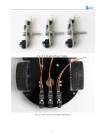
Страница 29: ...26 Fig 3 1 15 Diagram of Tracing Module Installation...
Страница 30: ...27 Fig 3 1 16 Diagram of Screw Brackets Fig 3 1 17 The Back of Complete Installation...
Страница 32: ...29 First install the screws on the UNO After the completion as shown...
Страница 33: ...30 Then install UNO on acrylic plates Fig 3 1 20 Diagram of Arduino Mainboard and Battery Box Installation...
Страница 43: ...40 Fig 3 1 33 Diagram of Wires Arrangement Fig3 1 34 the Effect of Whole Assembly...
Страница 56: ...53 Fig 3 2 11 Diagram of Data with Obstacles Fig 3 2 12 Diagram of Data without Obstacles...
Страница 69: ...66 Fig 3 2 22 Diagram of Steering Gear Fig 3 2 23 Composition of Steering Gear...
Страница 93: ...90 Fig 3 2 42 Receiving Head Position Fig 2 3 43 Installation of Receiving Head...


