92
4, Opening the "remote control testing program" in the CD, and copying the library folder (PS2X_lib) to the
"libraries"folder in the Arduino IDE installation path, as shown in Fig.2.4.14, otherwise the compiler cannot
pass. In addition, downloading the program to the Arduino development board, opening the PS2 remote
control, if the receiving head and remote control has been connected (or pairing successfully), the receiver
head indicator will always be on, otherwise the LED lights will flash constantly. Finally, we open the serial
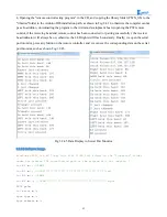
port monitor, press any button on the remote controller, and we can see the corresponding data on the serial
port monitor, such as shown Fig.3.2.45.
Fig.3.2.45 Data Display in Serial Port Monitor
3.2.6.5 Software Design
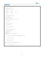
#include <PS2X_lib.h>
/*
Copy this file (PS2X_lib) folder to the "libraries" folder
under the Arduino IDE installation path or the program will not compile. * /
int
E1
=
5
;
//PWMA
int
M1
=
9
;
//DIRA****************************************left
int
E2
=
6
;
//PWMB
int
M2
=
10
;
//DIRB****************************************right
PS2X ps2x
;
int
error
=
0
;
byte type
=
0
;
byte vibrate
=
0
;
Содержание Hummer-Bot
Страница 1: ...Hummer Bot Instruction Manual Github https github com keywish keywish hummer bot...
Страница 7: ...4...
Страница 8: ...5...
Страница 9: ...6...
Страница 10: ...7...
Страница 13: ...10 Fig 2 2 Several commonly usedArduino...
Страница 15: ...12 After the completion as shown...
Страница 16: ...13 The second step is to Welding wire on the motor...
Страница 17: ...14 After the completion as shown...
Страница 19: ...16 Fig 3 1 3 Diagram of Aluminum Alloy Bracket Installation...
Страница 20: ...17 Fig 3 1 4 Diagram of Motor Installation Fig 3 1 5 Fixing Screw for Motor...
Страница 24: ...21 Fig 3 1 10 Diagram of Wheel Installation Fig 3 1 10 Diagram of Wheel Screw Fixation...
Страница 29: ...26 Fig 3 1 15 Diagram of Tracing Module Installation...
Страница 30: ...27 Fig 3 1 16 Diagram of Screw Brackets Fig 3 1 17 The Back of Complete Installation...
Страница 32: ...29 First install the screws on the UNO After the completion as shown...
Страница 33: ...30 Then install UNO on acrylic plates Fig 3 1 20 Diagram of Arduino Mainboard and Battery Box Installation...
Страница 43: ...40 Fig 3 1 33 Diagram of Wires Arrangement Fig3 1 34 the Effect of Whole Assembly...
Страница 56: ...53 Fig 3 2 11 Diagram of Data with Obstacles Fig 3 2 12 Diagram of Data without Obstacles...
Страница 69: ...66 Fig 3 2 22 Diagram of Steering Gear Fig 3 2 23 Composition of Steering Gear...
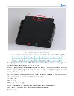
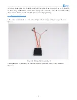
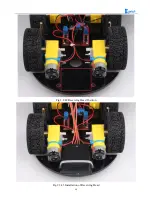
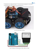
Страница 93: ...90 Fig 3 2 42 Receiving Head Position Fig 2 3 43 Installation of Receiving Head...


