86
analogWrite
(
M1
,
val
);
//the speed value of motorA is val
analogWrite
(
E2
,
0
);
analogWrite
(
M2
,
val
);
//the speed value of motorA is val
irrecv
.
resume
();
//
接收下一个值
}
Serial
.
println
(
results
.
value
,
HEX
);
// Output the receive code in hexadecimal
Serial
.
println
();
// Add a blank line for easy viewing of the output
irrecv
.
resume
();
}
}
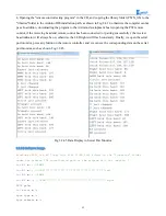
The above is the infrared remote reference program, you can open it in the CD and download to the
development board, the instructions of remote control in shown in Fig.3.2.38.
Fig.3.2.38. Infrared Remote Control Instructions
3.2.6 PS2 Handle (Optional)
3.2.6.1 Suite Introduction
PS2 handle is SONY game remote control handle, SONY series game host is very popular in the world.
Someone has come up with the idea of the PS2 handle, cracked the communication protocol, so that the
handle can be connected to other devices for remote control, such as remote control of our familiar four
wheeled vehicles and robots. Its outstanding features are cost-effective,rich buttons and easy to extend to
other applications, Fig.3.2.39 shows a commonly used PS2 wireless handle.
Содержание Hummer-Bot
Страница 1: ...Hummer Bot Instruction Manual Github https github com keywish keywish hummer bot...
Страница 7: ...4...
Страница 8: ...5...
Страница 9: ...6...
Страница 10: ...7...
Страница 13: ...10 Fig 2 2 Several commonly usedArduino...
Страница 15: ...12 After the completion as shown...
Страница 16: ...13 The second step is to Welding wire on the motor...
Страница 17: ...14 After the completion as shown...
Страница 19: ...16 Fig 3 1 3 Diagram of Aluminum Alloy Bracket Installation...
Страница 20: ...17 Fig 3 1 4 Diagram of Motor Installation Fig 3 1 5 Fixing Screw for Motor...
Страница 24: ...21 Fig 3 1 10 Diagram of Wheel Installation Fig 3 1 10 Diagram of Wheel Screw Fixation...
Страница 29: ...26 Fig 3 1 15 Diagram of Tracing Module Installation...
Страница 30: ...27 Fig 3 1 16 Diagram of Screw Brackets Fig 3 1 17 The Back of Complete Installation...
Страница 32: ...29 First install the screws on the UNO After the completion as shown...
Страница 33: ...30 Then install UNO on acrylic plates Fig 3 1 20 Diagram of Arduino Mainboard and Battery Box Installation...
Страница 43: ...40 Fig 3 1 33 Diagram of Wires Arrangement Fig3 1 34 the Effect of Whole Assembly...
Страница 56: ...53 Fig 3 2 11 Diagram of Data with Obstacles Fig 3 2 12 Diagram of Data without Obstacles...
Страница 69: ...66 Fig 3 2 22 Diagram of Steering Gear Fig 3 2 23 Composition of Steering Gear...
Страница 93: ...90 Fig 3 2 42 Receiving Head Position Fig 2 3 43 Installation of Receiving Head...


