2
This manual is a specifications for "Hummer-Bot" , the file whose format is PDF which is in the CD
along with our product requires the corresponding software to open. It contains detailed schematic diagrams
and complete source codes for all instances, the codes won't have any mistake under our strict test. In
addition, the library files used in the source codes are put into the corresponding path, you only need to see
corresponding phenomenon of the car and personally experience the process of experiment by downloading
the source codes to Arduino via the serial port emulator.
This manual is not only very suitable for students and electronic enthusiasts, but also a good reference
for companies to develop products.
1.2 Product Introduction
"Hummer-Bot" is a multifunctional car based on the Arduino UNO and L298N motor. Compared with
the traditional car, "Hummer-Bot" is also equipped with wireless control (Bluetooth, infrared, WIFI and so
on); ultrasonic; infrared. It can trace and avoid obstacles automatically, of course, makers can also
automatically control the car with wireless and make full use of each module, as well as integrate all kinds
of related sensors to make the car more intelligent, which is more challenging. "Hummer-Bot" has various
types of information, technical manuals, routines, etc., which can teach you step by step. Each electronic fan
can use it easily to achieve their desired function.
Product Features
◆
Three groups of black line infrared tracing module
◆
Two group of infrared obstacle avoidance module
◆
Ultrasonic obstacle avoidance
◆
Four DC motor drive
◆
Two 3000mZh, 3.7V rechargeable lithium battery with longer endurance
◆
Remaining capacity of battery real-time detection
◆
Infrared remote control
◆
Bluetooth app control
◆
PS2 handle control (optional)
Содержание Hummer-Bot
Страница 1: ...Hummer Bot Instruction Manual Github https github com keywish keywish hummer bot...
Страница 7: ...4...
Страница 8: ...5...
Страница 9: ...6...
Страница 10: ...7...
Страница 13: ...10 Fig 2 2 Several commonly usedArduino...
Страница 15: ...12 After the completion as shown...
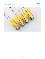
Страница 16: ...13 The second step is to Welding wire on the motor...
Страница 17: ...14 After the completion as shown...
Страница 19: ...16 Fig 3 1 3 Diagram of Aluminum Alloy Bracket Installation...
Страница 20: ...17 Fig 3 1 4 Diagram of Motor Installation Fig 3 1 5 Fixing Screw for Motor...
Страница 24: ...21 Fig 3 1 10 Diagram of Wheel Installation Fig 3 1 10 Diagram of Wheel Screw Fixation...
Страница 29: ...26 Fig 3 1 15 Diagram of Tracing Module Installation...
Страница 30: ...27 Fig 3 1 16 Diagram of Screw Brackets Fig 3 1 17 The Back of Complete Installation...
Страница 32: ...29 First install the screws on the UNO After the completion as shown...
Страница 33: ...30 Then install UNO on acrylic plates Fig 3 1 20 Diagram of Arduino Mainboard and Battery Box Installation...
Страница 43: ...40 Fig 3 1 33 Diagram of Wires Arrangement Fig3 1 34 the Effect of Whole Assembly...
Страница 56: ...53 Fig 3 2 11 Diagram of Data with Obstacles Fig 3 2 12 Diagram of Data without Obstacles...
Страница 69: ...66 Fig 3 2 22 Diagram of Steering Gear Fig 3 2 23 Composition of Steering Gear...
Страница 93: ...90 Fig 3 2 42 Receiving Head Position Fig 2 3 43 Installation of Receiving Head...


