46
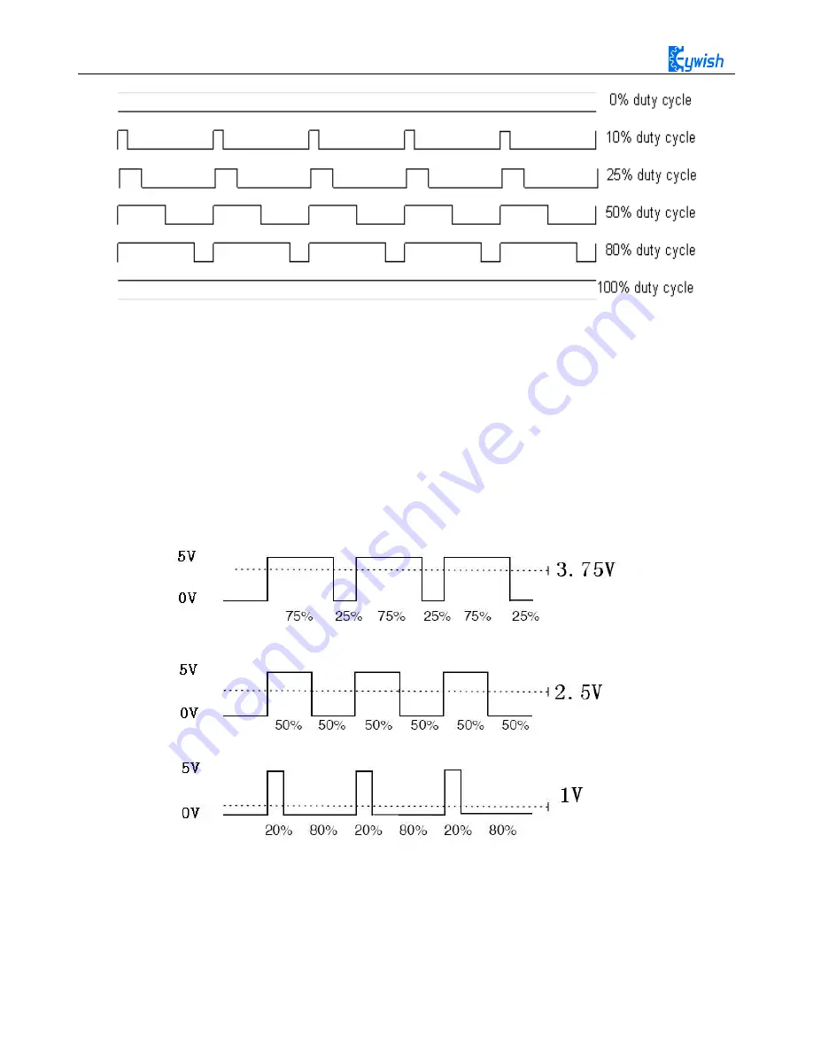
Fig.3.2.5 Sequence Diagram of PWM Duty Cycles
In Arduino, analog voltage can not be output, only 0 or 5V digital voltage value, we can use high
resolution counter and the duty cycles of the square wave modulation method to encode a specific level of
analog signal. The PWM signal is still digital, because at any given time, the full amplitude of DC power
supply is either 5V (ON) or 0V (OFF). The voltage or current source is added to the analog load with a ON
or OFF repetitive pulse sequence. When the DC power supply is added to the load, the power supply is on,
otherwise the power supply is off. As long as the bandwidth is enough, any analog value can use PWM to
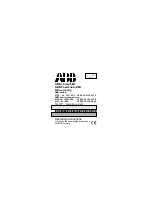
encode. The output voltage value is calculated by the on and off time. Output voltage = (turn-on time / pulse
time) * maximum voltage. Fig.2.4.6 shows the corresponding voltage to the pulse change.
Fig.2.4.6 Relation between Pulse and Voltage
In the "Hummer-Bot" car experiment, we use Arduino UNO R3 as the main control board. By referring
to the chip data, we will know that Arduino UNO has 6 PWM pins, namely digital interfaces 3, 5, 6, 9, 10,
11, and we select 5, 6, 9, 10 as the motor control IO, the connection is shown in Fig.2.4.7.
Содержание Hummer-Bot
Страница 1: ...Hummer Bot Instruction Manual Github https github com keywish keywish hummer bot...
Страница 7: ...4...
Страница 8: ...5...
Страница 9: ...6...
Страница 10: ...7...
Страница 13: ...10 Fig 2 2 Several commonly usedArduino...
Страница 15: ...12 After the completion as shown...
Страница 16: ...13 The second step is to Welding wire on the motor...
Страница 17: ...14 After the completion as shown...
Страница 19: ...16 Fig 3 1 3 Diagram of Aluminum Alloy Bracket Installation...
Страница 20: ...17 Fig 3 1 4 Diagram of Motor Installation Fig 3 1 5 Fixing Screw for Motor...
Страница 24: ...21 Fig 3 1 10 Diagram of Wheel Installation Fig 3 1 10 Diagram of Wheel Screw Fixation...
Страница 29: ...26 Fig 3 1 15 Diagram of Tracing Module Installation...
Страница 30: ...27 Fig 3 1 16 Diagram of Screw Brackets Fig 3 1 17 The Back of Complete Installation...
Страница 32: ...29 First install the screws on the UNO After the completion as shown...
Страница 33: ...30 Then install UNO on acrylic plates Fig 3 1 20 Diagram of Arduino Mainboard and Battery Box Installation...
Страница 43: ...40 Fig 3 1 33 Diagram of Wires Arrangement Fig3 1 34 the Effect of Whole Assembly...
Страница 56: ...53 Fig 3 2 11 Diagram of Data with Obstacles Fig 3 2 12 Diagram of Data without Obstacles...
Страница 69: ...66 Fig 3 2 22 Diagram of Steering Gear Fig 3 2 23 Composition of Steering Gear...
Страница 93: ...90 Fig 3 2 42 Receiving Head Position Fig 2 3 43 Installation of Receiving Head...


