U3042AE16
Hardware Lock-link Installation (U3021-60004)
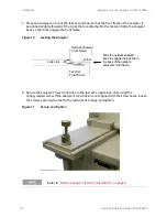
4. Install the lower lock-links (N5242-20210, right and N5242-20211, left not shown) onto the
analyzer, as shown in
.
Figure 8
Install Lock-links to the Analyzer
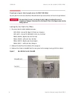
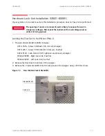
5. Remove the two upper standoffs from the rear panel of the test set using a T20 torx driver.
6. Install the left and right lock-links onto the test set, as shown in
Figure 9
Install Lock-links to the Test Set
Lock-link (N5242-20210)
Right
Screw 0515-1619
T20 M4x0.7 25 mm (x2)
N5242-20208
N5242-20209
Right lock-link
Left lock-link
Screw 0515-2317 (x2)
T15 M3.5X0.6 12 mm
User's and Service Guide U3042-90012
15


