U3042AE16
Troubleshooting the Test Set
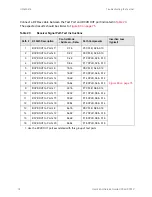
Connect a RF Flex cable between the Test Port and RCVR OUT port indicated in
.
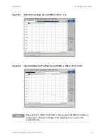
The expected results should be similar to
Table 23
Receiver Signal Path Test Instructions
Path #
RF Path Description
Control Mode
<Address>.<Data>
Path Components
Insertion Loss
(typical)
1
RCVR OUT to Ports 5
1
1. Use the RCVR OUT port associated with this group of test ports.
0.16
P5 CPLR, S2 & S10
2
RCVR OUT to Ports 9
0.32
P9 CPLR, S2 & S10
3
RCVR OUT to Ports 13
0.48
P13 CPLR, S2 & S10
4
RCVR OUT to Ports 17
0.64
P17 CPLR, S2 & S10
5
RCVR OUT to Ports 6
16.16
P6 CPLR, S4 & S12
6
RCVR OUT to Ports 10
16.32
P10 CPLR, S4 & S12
7
RCVR OUT to Ports 14
16.48
P14 CPLR, S4 & S12
8
RCVR OUT to Ports 18
16.64
P18 CPLR, S4 & S12
9
RCVR OUT to Ports 7
32.16
P7 CPLR, S6 & S14
10
RCVR OUT to Ports 11
32.32
P11 CPLR, S6 & S14
11
RCVR OUT to Ports 15
32.48
P15 CPLR, S6 & S14
12
RCVR OUT to Ports 19
32.64
P19 CPLR, S6 & S14
13
RCVR OUT to Ports 8
64.16
P8 CPLR, S8 & S16
14
RCVR OUT to Ports 12
64.32
P12 CPLR, S8 & S16
15
RCVR OUT to Ports 16
64.48
P16 CPLR, S8 & S16
16
RCVR OUT to Ports 20
64.64
P16 CPLR, S8 & S16
74
User's and Service Guide U3042-90012


