U3042AE16
Controlling the Test Set with N5222/32/42A/B
This first command creates a new S10_10 measurement on channel 1
of the PNA-X, named “ch1_S10_10,” and configures the internal Test
Set RF switches.
CALC1:PAR:EXT 'ch1_S10_10', 'S10_10'
This second command feeds the newly created measurement named
“ch1_S10_10” to trace 2 on the PNA-X so that it will be displayed on
the PNA-X screen.
DISP:WIND1:TRAC2:FEED 'ch1_S10_10'
NOTE: Here are syntax format examples for single digit S-parameters:
‘ch1_S99’
‘ch1_S22’
‘ch1_S9_10’ ‘ch1_S10_9’
Method 2 - Using the Test Set Address and Data Values
This method is available while the system is in Standalone mode
only.
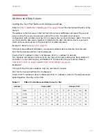
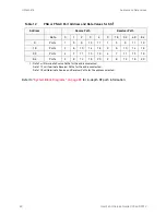
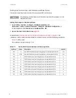
The Address and Data values for the Test Set can be found in the
“Address and Data Values” section on page
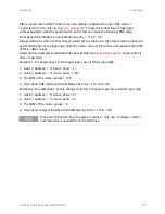
The Test Set internal switch settings are programmed into the
firmware of the Test Set and can be controlled with the specific
Address and Data values. Each Address and Data value pair sets the
Source or Receiver switch paths. For an S-parameter measurement,
two pairs of Address and Data values will be needed.
Address and Data values are separated by a comma. Commands
should be separated by a new line, or carriage return.
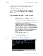
For example:
CONT:EXT:TEST:DATA <address>,<data>
CONT:EXT:TEST:DATA 0,0
Example: CONT:EXT:TEST:DATA 0,0
Figure
44
Method 2 - Using Test Set Address and Data Values
46
User's and Service Guide U3042-90012

