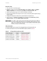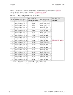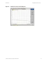
U3042AE16
Troubleshooting the Test Set
Non-RF Failures
Non RF failures are; Power Supply, Fans, Control Lines, Status LEDs or Interface not operating.
Refer to
.
1.
Verify that the front panel Power Switch is operational.The front panel Active LED will be
off
unless the test set interface cable is connected and the test set is addressed by the network
analyzer.
2.
Turn on the Standby Switch.
3.
The rear panel, Deck and Internal power supply fans should be operational. If not continue
.
4.
AC Line voltage checks (remove AC power from the instrument).
a.
Ensure the proper AC Line voltage is present at the instrument line cord.
b.
Remove the AC power cord from the instrument. Verify the instrument AC Line Module
fuse (2119-0709) and replace if necessary. Refer to
c.
Verify the Internal AC lines fuse (2110-0342). Remove the instrument bottom cover. Near
the rear panel are two fuse holders, verify the fuses and replace if necessary. See
5.
Internal DC Power checks.
a.
Set the front panel switch to the Standby position. No fans or indicator lights should be
operational.
b.
Remove the top cover.
c.
Set the Standby switch to the
on
position. Both the rear panel and internal power supply
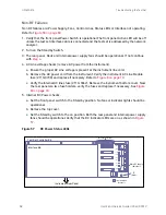
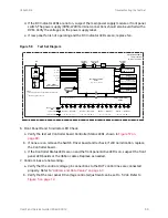
fans should be operational. Verify that the DC indicator LEDs are
on
as shown in
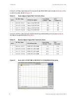
Figure 5
7
DC Power Status LEDs
Interface Bd.
+5v
+24v
+3v
-15v
-12v
+15v
+12v
-10v
+9v
Test Set Controller Bd.
= LED INDICATOR
(DC Power)
Instrument Rear Panel
TP2
Main DC Supply
Indicators
TP
(GND)
Controller Status LEDs
68
User's and Service Guide U3042-90012

