


KLR-DEV 060713
5-9
5.5
DEMONSTRATION PROGRAM USING THE VXI
PLUG&PLAY
DRIVER
The demonstration program is intended to illustrate the use of the VXI
plug&play
functions
included with the KLR power supply. The demonstration program is installed under Windows by
running SETUP.EXE. The program as written presents a virtual front panel for control of a single
KLR power supply
The following paragraphs describe the windows and the associated controls and indicators pro-
vided with the demonstration program. For additional details regarding operation of the KLR,
refer to the operating instructions for local and remote mode found in the KLR User Manual.
5.5.1
INSTRUMENT SETUP
NOTE: Please ensure that all programming connections (GPIB or RS 232 as applicable) are in
place before switching the power supply on. Before running the program, verify the
GPIB address and adjust if necessary. For RS 232 communications the power supply
must be set to 38400 baud. Ethernet programming is not supported.
After the program is installed, double clicking KLRCTRL.exe starts the program and opens the
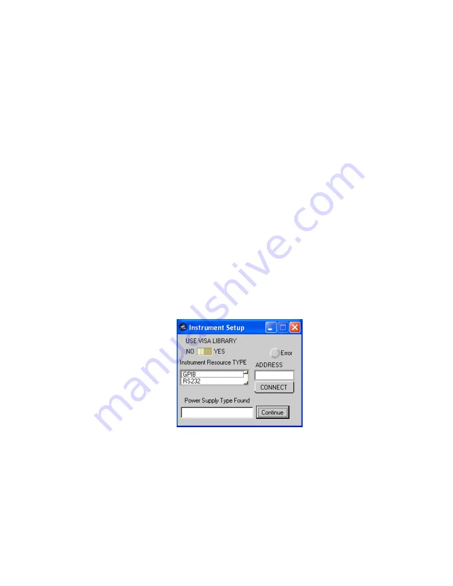
Instrument Setup window (see Figure 5-4). Select the appropriate communications method
(TYPE) from the Instrument Resource list provided. If GPIB is selected, enter the correspond-
ing GPIB address in the box labeled ADDRESS. If RS 232 is selected, enter the number of the
communications port used (e.g., for COM1 enter "1"). Click the CONNECT button to establish
communication with the power supply. If successful, the power supply model number is dis-
played in the box labeled POWER SUPPLY TYPE FOUND. If not, the Error indicator is red and
an error message is displayed in the box. The most common errors are incorrect GPIB address
or improper baud rate setting (RS 232). If the power supply displayed is correct, click the Con-
tinue button to open the main panel (Figure 5-5).
FIGURE 5-4. INSTRUMENT SETUP WINDOW
Содержание KLR SERIES
Страница 2: ......
Страница 10: ......
Страница 42: ......
Страница 58: ...4 16 KLR DEV 060713 FIGURE 4 10 FUNCTION GENERATOR PANEL FIGURE 4 11 CONFIGURE User Sequence vi BLOCK DIAGRAM ...
Страница 59: ......
Страница 60: ......
Страница 61: ...FIGURE 4 13 FUNCTION GE ...
Страница 62: ......
Страница 86: ......
Страница 90: ......


