CAN Master/Slave
Kendrion Kuhnke Automation GmbH
428
17 May 2021
Terminals
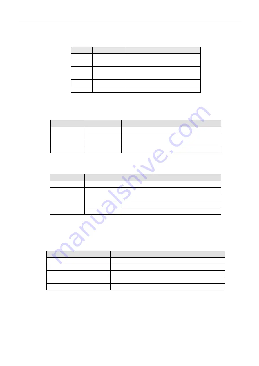
IO Connection, 18-pin, Male
Trm.
Signal
Explanation
0
CAN-H
CAN-High Signal
1
CAN-L
CAN-Low Signal
2
CAN-GND
earth potential
3
CAN-H Term.
Bus termination CAN-H
4
CAN-L Term.
Bus termination CAN-L
5..15
-
Not used
Status LEDs
LED "EtherCAT Run"
The LED labelled "RN" indicates the state of the EtherCAT ASIC.
Initialising, no data exchange
Pre-operational, no data exchange
Safe operation, inputs readable
Operational, unrestricted data exchange
LED "IO"
The LED labelled "IO" indicates the state of the module's I/Os.
State
LED flash code
Explanation
Ok
Green, on
No error
Error
Red, 4x
EtherCAT watchdog
Red, 5x
Transmit queue overflow
Red, 6x
Receive queue overflow
Red, 7x
No Tx counter
LED "Power"
Not used
LEDs "Channel [COM State]"
The "Channel" LEDs indicate the state of every channel.
LED colour, flash code
Explanation
Off
No communication
Green, flashing
Communication
Alternating red/green, flashing
CAN warning while communicating
Red, flashing
CAN warning
Red, on
CAN Bus Off
Process Image
There are 20 PDOs containing 8 bytes of data each for every direction. Use PDO Assignment (objects 1C12
and 1C13) to vary the volume of data. Taken together with the mailboxes (32 bytes each), this is the
maximum configuration of ET1200.


