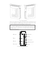
(C) The external control box is installed; please note the table right side leaving enough space. The control
box is locked in the lower right
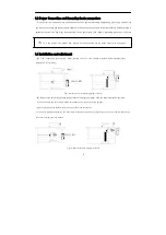
(D) The pedal (speed controller) is installed; please keep the boom into a straight line, the foot board support
locking in the table below. And according to need, adjust the screw, change the angle of the foot pedal, the
pedal feet step on and after stroke is suitable for the operation habit.
2 Operation Panel Instruction
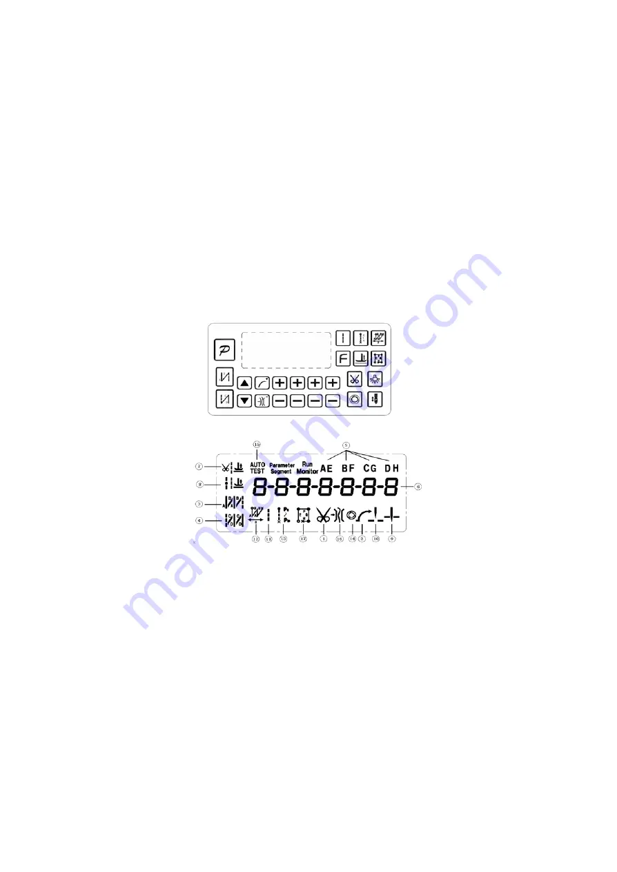
2.1 Operation panel display instruction
According to the different configuration and demand, AS series controller provides many kinds of operation
panel for customers to use. According to the operating condition of the system, the LCD module operation
panel will display the sewing patterns, various parameters, front / back fixed seam to set the current, and the
presser foot, needle position, line cutting, slow up the joint character LCD. Each panel contains the function
keys and liquid crystal display function symbols according to the type of distinction and slight increase or
decrease, but the work mode and use are roughly the same.
1
)
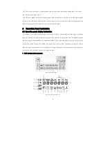
H-43 Operation panel appearance
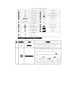
Fig.2-1 H-43 appearance
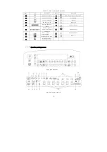
Fig.2-2 H-43 LCD screen icon
4

