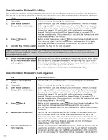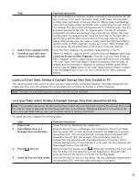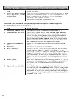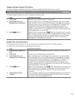
22
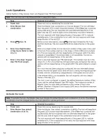
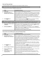
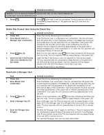
Step
Detailed Instructions
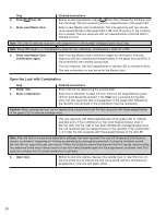
4.
Enter new Service User
Enter the Service User combination (1–8 digits depending on combination.
the maximum number of Keypad Users allowed and the Keypad User PIN
field length). The lock responds with two beeps/flashes of the green LED if
the User ID portion of the com bi na tion is unique. The lock responds with two
beeps/flashes of the red LED to indicate an error.
Note: The User ID selected must be in the range from 0 to the number of keypad users minus one.
Note: When PIN length = 0, Combination = User ID only; otherwise, Combination = User ID + PIN. Do not set
Service User PIN to all 0’s.
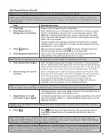
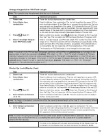
5.
Enter Service User
Enter the Service User combination again for verification. The lock responds
combination again.
responds with two si mul ta neous beeps/flashes of the green and red LEDs if
the com bi na tion was verified suc cess ful ly. The lock responds with two
beeps/flashes of the red LED to indicate an error.
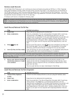
6.
Enter one-digit user access
Enter a one-digit user access schedule in the range of 0–6. The lock
schedule (0–6).
responds with two simultaneous beeps/flashes of the green and red LEDs if
the access schedule des ig na tion is valid. The lock responds with two beeps/
flashes of the red LED if the access sched ule designation is invalid. Refer to
the “Access Schedules” section on page 8 for more detailed in for ma tion.
Note: If the value of “0” is assigned for the access schedule, the user can access the lock at all times. To assign a
value other than “0”, defined access schedules must have been downloaded from the PC.
A Service User is now activated with the entered combination.
Note: The PIN portion of the combination issued to the Service User cannot be changed.
Note: The Service User is removed from the lock either by use of the issued combination or by the Master User
or a Man ag er User via Keypad Command 30.
Remove Service User Combination
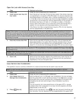
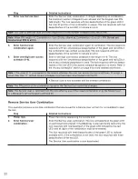
This operation removes a one-time combination that was issued for a Service User so that it is not avail able to open
the lock.
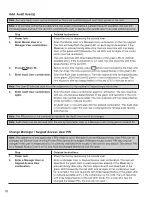
Step
Detailed Instructions
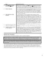
1.
Power lock.
Power the lock by depressing the outside lever.
2.
Enter Service User
Enter the Service User combination. The lock will beep/flash the green LED
combination.
on each key stroke entered. If the Clear key is pressed during data entry, the
lock responds with one beep/flash of the green LED followed by the red
LED, and all digits of the combination must be re-entered.
The lock responds with three beeps/flashes of the green LED to indicate
avail able entry. If the com bi na tion is not valid, the lock responds with three
beeps/flashes of the red LED.
The Service User com bi na tion is now de ac ti vat ed.
Содержание PowerLever 455 Series
Страница 1: ...PowerLever 455x Operating Instructions...
Страница 37: ...37 Notes...
Страница 38: ...38 Notes...
Страница 39: ...39 Notes...

