
30.08.2017
1
5
2
3
SHERIFF-5
ELECTROMECHANICAL LOCK
FOR PLASTIC DOORS AND WINDOWS
OPERATING MANUAL
TU 3428 – 003 – 80210527 – 14
1.
APPLICATION
Electromechanical lock "Sheriff-5" is designed for locking hinged plastic doors and windows, opening inward and outward, with
a possibility of remote opening them with the controllers of access control systems, audio and video door phones, code access
panels. The lock is made in the normally open type (or fail-safe), it is open when the voltage supply is off, and that provides
evacuation during emergencies complied with the power outage. The lock may be installed on doors and windows, both on the right
and the left ones.
2.
OPERATING CONDITIONS
Climatic operating conditions:
- ambient air temperature: from -40 to +50°
С
;
- relative air humidity not more than 95% at +35°
С
and with lower temperatures without condensation and frost formation;
- installing indoors in any type of doors;
- resistance to the environmental exposure complies with GOST 15150-69:UHL2.
Operation of the lock at low temperatures is possible when most of the time the lock is open (voltage supply is on).
During the operation, prevent the ingress of water and dust into the lock.
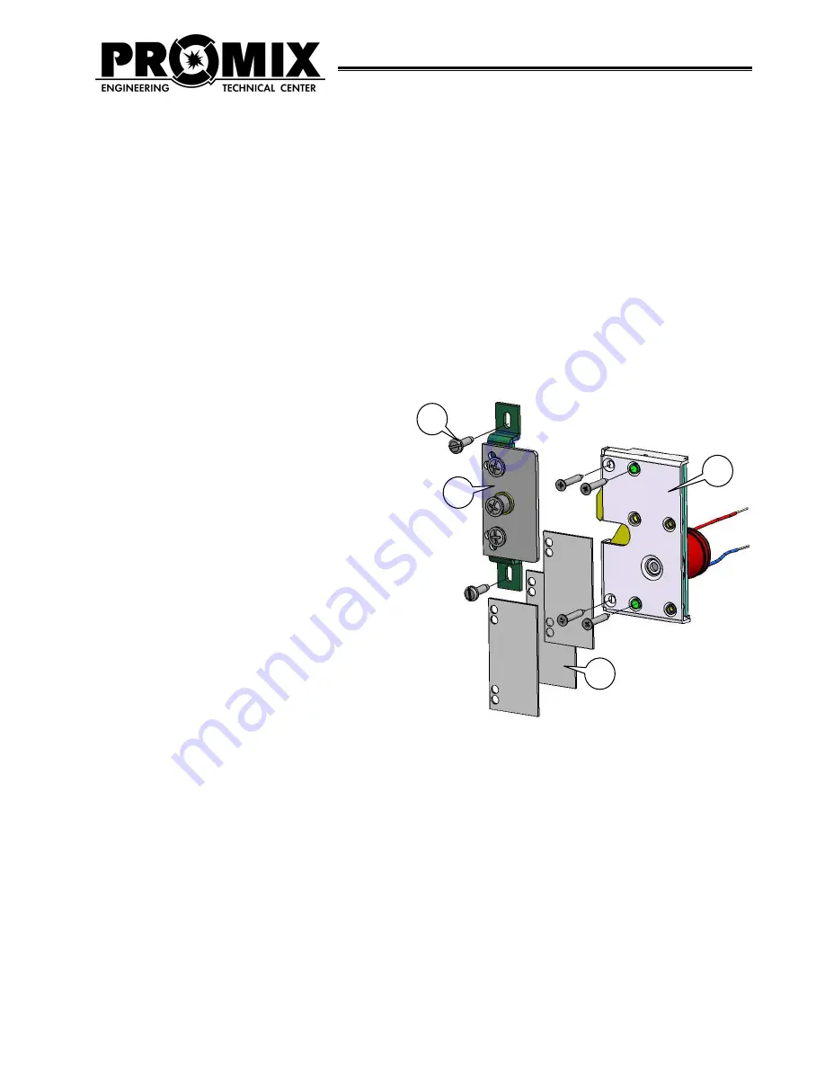
3.
DELIVERY SET
1
Electromechanical lock
1 pc.
2
Deadbolt assembled with the plate
1 pc.
3
Gasket
3 pc.
4
Screw 3
х
30 for lock fixing
4 pcs.
5
Self-drilling screw 3.5
х
25 for deadbolt fixing
2 pcs.
Check completeness of the delivery set while purchasing.
TECHNICAL SPECIFICATIONS
Holding force, kg, no less than. . . . . . . . . . . . . . . . . . 300,
DC voltage supply, V. . . . . . . . . . . . . . . . . . . . . . . 12,
Voltage supply range, V. . . . . . . . . . . . . . . . . . . . . 11÷14,
Current consumption (12V), m
А
, not more than. . . . . . . . . .100,
Permissible clearance between the door leaf and frame, mm . . 10÷15
Weight, kg . . . . . . . . . . . . . . . . . . . . . . . . . . . . .0.3
Power cable length, m . . . . . . . . . . . . . . . . . . . . . . . 0.1
Ensure correct polarity during lock installation.
Red (light) – positive, black (dark) – negative.
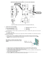
4. OPERATING PRINCIPLE AND DESIGN FEATURES
The lock mechanism contains two devices: the fixation device of the deadbolt roller and the blocker of the fixation device
(see Fig.1). The fixation device holds the deadbolt, and the blocker shuts the deadbolt in the lock. When the door is being closed
the roller fits into the groove of the lock, and having overcome the fixation device's effort, it fixes into the lock. The fixation device
provides only holding the roller in the lock, and when the voltage supply is off, the roller may enter and egress from the lock,
having overcome the fixation's effort. This ensures fixation of the closed door when the lock is open. When the voltage supply is
on, the fixation device is being blocked and it shuts the deadbolt in the lock.
When the voltage supply is off, the blocker releases the fixation device, and for opening the door, it is necessary to
overcome the fixation's effort.
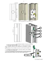
The adjusting holes in the deadbolt bracket serve for correction of the roller position in relation to the groove of the lock in
the vertical direction (for example, when the door is sagging) and in the horizontal direction. The gaskets are used for correction of
the roller position depending on the clearance between the door frame and the door.