


CHAPTER 9: Troubleshooting
54
Chassis and Interface Alarm Messages
Copyright © 2010, Juniper Networks, Inc.
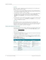
Port LEDs
LEDs on the front panel of the gateway display system status and alert you to troubleshoot the
gateway. These LEDs include the following:
z
T1/E1 port LEDs—Two LEDs (yellow and green) on top of each T1/E1 port indicate the status of
each T1/E1 port that is labeled from
0
through
15
. At any one time, only one of the LEDs is lit. For
more information on LEDs, see “T1/E1 Ports” on page 6.
z
Copper Ethernet port LEDs—Two LEDs (yellow and green) on the top of each copper Ethernet
port indicate the status of each Copper Ethernet port and are labeled as
COPPER
with
ETHERNET 0
through
ETHERNET 2.
For more information on LEDs, see “Ethernet Ports” on
z
Optical Ethernet port LEDs—Two LEDs (yellow and green) on top of each SFP indicate the status
of each SFP and are labeled as SFP with
ETHERNET 1
and
ETHERNET 2
. For more information
on LEDs, see “Ethernet Ports” on page 8.
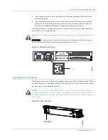
System LED
One system LED on the center of the front panel indicates the status of the gateway. Green
indicates that the gateway is functioning normally. Red indicates a critical condition that can cause
the gateway to stop functioning. Yellow indicates a non-critical or minor condition that requires
monitoring. For more information, see System LED on page 54.
Chassis and Interface Alarm Messages
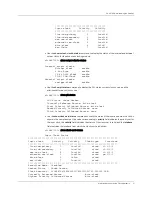
When the gateway detects an alarm condition, it lights the red or the yellow alarm LED. To view a
more detailed description of the cause for the alarm, issue the
show chassis alarms
command:
cli@BX7000>
show chassis alarms
There are two classes of alarms:
z
Chassis alarms—Indicate a problem with a chassis component such as power supply and board
temperature, as described in Table 16 on page 54.
z
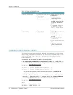
Interface alarms—Indicate a problem with a specific network interface, as described in Table 17.
In Table 17 on page 55, the text in the column labeled
CLI Message
appears in the output from the
show chassis alarms
command.
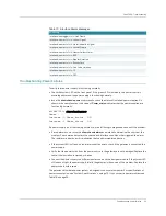
Table 16: Chassis Alarm Messages
Chassis
Component
Alarm Condition
Remedy
Alarm Severity
Power
supplies
A power supply has
been removed
Insert missing power supplies
Red/yellow/ignore as you
configure
A power supply has
failed
Replace failed power supply
Red/yellow/ignore as you
configure
Only one power
supply is operating
Insert or replace secondary
power supply
Red/yellow/ignore as you
configure
Temperature
The chassis
temperature has
exceeded the
threshold (Default
threshold: 80° C).
Check room temperature
Red
Содержание BX7000
Страница 10: ... x Copyright 2010 Juniper Networks Inc ...
Страница 12: ... xii Copyright 2010 Juniper Networks Inc ...
Страница 18: ...About This Guide xviii Requesting Support Copyright 2010 Juniper Networks Inc ...
Страница 20: ... 2 Copyright 2010 Juniper Networks Inc ...
Страница 36: ...CHAPTER 1 BX7000 Multi Access Gateway Overview 18 Advanced Clocking Module Copyright 2010 Juniper Networks Inc ...
Страница 60: ...CHAPTER 6 Grounding and Powering the Gateway 42 Powering Off the Gateway Copyright 2010 Juniper Networks Inc ...
Страница 64: ...CHAPTER 7 Accessing and Configuring the Gateway 46 Initial Setup Copyright 2010 Juniper Networks Inc ...
Страница 66: ... 48 Copyright 2010 Juniper Networks Inc ...
Страница 76: ...CHAPTER 9 Troubleshooting 58 Troubleshooting the Advanced Clocking Module Copyright 2010 Juniper Networks Inc ...
Страница 90: ... 72 Copyright 2010 Juniper Networks Inc ...
Страница 122: ... 104 Hardware Compliance Copyright 2010 Juniper Networks Inc ...
Страница 131: ...Copyright 2010 Juniper Networks Inc 113 Appendix E Declaration of Conformity ...
Страница 132: ... 114 Copyright 2010 Juniper Networks Inc ...
Страница 133: ...Copyright 2011 Juniper Networks Inc 115 PART 4 Index z Index on page 117 ...
Страница 134: ... 116 Copyright 2010 Juniper Networks Inc ...