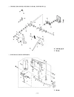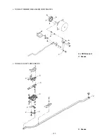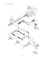
– 176 –
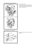
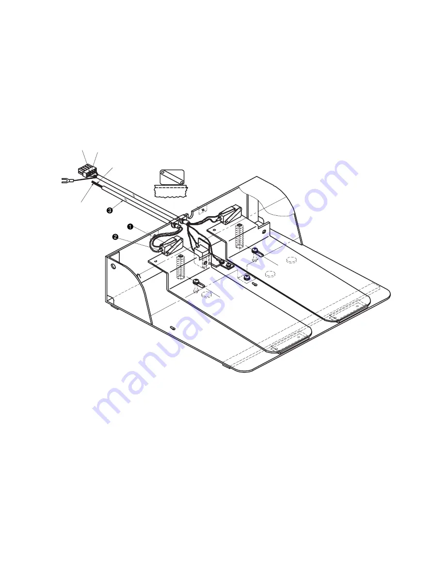
6. Switch mounting position diagram.
(Caution) The micro switch shall be mounted in parallel to the upper plane
of the pedal.
(The switch is fixed in the ON state.)
CN88
Connector
Connector pin
No. 2
Connector pin
No. 7
Black : No. 7
White : No. 2
5. Operation control items
o The moving switch does not function unless the right pedal is trodden first.
o For more details, refer to [6. Switch mounting position diagram].
Содержание AMS-221EHL
Страница 185: ... 181 A JUKI Grease A B JUKI Grease B C Grease A A A A A A A B C C B B B B o MAIN SHAFT NEEDLE BAR COMPONENTS ...
Страница 190: ... 186 o X Y COMPONENTS 1 E C C C C C Grease E Three Bond 3060G Locktight 241 ...
Страница 191: ... 187 o X Y COMPONENTS 2 D D C C C D C C D C Grease D Grease D Locktight 241 ...
Страница 192: ... 188 C Grease D Grease D D C D C C D C D D C C D D D D D C D C o CLOTH FEED MECHANISM COMPONENTS D ...
Страница 231: ... 7 MAIN PANEL board circuit diagram 227 PANEL BOARD MAIN BOARD ...


