


– 8 –
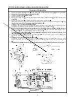
(4) Main shaft connection/disconnection
1. Loosen the setscrew
securing the main shaft counterbalance
, and remove the taper screw
.
2. Loosen 2 setscrews
(through the screwdriver hole A), 2 setscrews
, and 2 setscrews
.
On this occasion, loosen No. 2 setscrew first, and completely remove No. 1 setscrew from the flat part of the
main shaft
.
3. Remove the main shaft motor
.
Refer to “3.-(5) Removal of the main shaft motor and coupling”.
4. Loosen 2 setscrews
.
On this occasion, be aware that the balancer
may rotate due to loosened setscrews
.
5. Loosen 2 setscrews
.
6. Loosen 2 setscrews
.
On this occasion, completely remove No. 1 setscrew of the setscrews
from the flat part of the main shaft
.
7. Loosen 2 setscrews
and 2 setscrews
.
8. Pull out the main shaft
in the direction of Arrow C.
Screwdriver hole A
No. 1 setscrew
No. 2 setscrew
No. 2 setscrew
No. 2 set
screw
No. 1 setscrew
No. 1 setscrew
D
F
E
C
Procedures of disassembling
Main shaft taper hole
Содержание AMS-221EHL
Страница 185: ... 181 A JUKI Grease A B JUKI Grease B C Grease A A A A A A A B C C B B B B o MAIN SHAFT NEEDLE BAR COMPONENTS ...
Страница 190: ... 186 o X Y COMPONENTS 1 E C C C C C Grease E Three Bond 3060G Locktight 241 ...
Страница 191: ... 187 o X Y COMPONENTS 2 D D C C C D C C D C Grease D Grease D Locktight 241 ...
Страница 192: ... 188 C Grease D Grease D D C D C C D C D D C C D D D D D C D C o CLOTH FEED MECHANISM COMPONENTS D ...
Страница 231: ... 7 MAIN PANEL board circuit diagram 227 PANEL BOARD MAIN BOARD ...