– 105 –
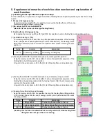
(3) Bank function setup
The bank function means a function of sewing effected through changeover to a pattern by an external signal,
which is registered in multiple pattern buttons in cases of cassette discrimination and others.
For sewing by the bank function, an external signal input is entered before the feeding frame is lowered at the
time of pedal treading-on. According to the input condition, a maximum of 16 patterns can be used for changeover.
When the bank function is used, the fixed refuge position preset in regard to “5.-(2) Fixed escape position
setting” is automatically enabled.
The reason is that the feeding frame in ordinary operation is made ready at the start of sewing (or the second
origin). This function is always possible if there is only one sewing pattern. In the case of the bank function,
however, the next sewing pattern is not always coinciding with the previous sewing pattern (or the second
origin) at the start of sewing. Therefore, it is necessary to use this refuge position function to secure the same
standby position for the feeding frame.
1. It is not always necessary to set up the memory switch K90 because the fixed refuge position mode is automati-
cally secured for the bank function.
2. The fixed refuge position, defined by the fixed refuge position Coordinate X of Memory Switch K117 and the fixed
refuge position Coordinate Y of Memory Switch K118, is regarded as the standby position of the feeding frame
for the bank function.
In standard setting, the feeding frame stops at the origin because the conditions are set at X:0 and Y:0. An
arbitrary position can be set up with the memory switches K117 and K118.
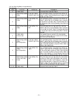
The bank functions and the input terminals can be set up with the following memory switches:
(1) Bank function setup
The memory switch K130 is used to set up the number of banks (quantity of input terminals).
Setup
Contents
Explanation
Bank disabled
The bank function is not used.
No. of banks 2
Two patterns are set for the number of banks.
One Input Terminal 0 is used.
No. of banks 4
Four patterns are set for the number of banks.
Two Input Terminal 0 to 1 are used.
No. of banks 8
Eight patterns are set for the number of banks.
Three Input Terminal 0 to 2 are used.
No. of banks 16
Sixteen patterns are set for the number of banks.
Four Input Terminal 0 to 3 are used.
Содержание AMS-221EHL
Страница 185: ... 181 A JUKI Grease A B JUKI Grease B C Grease A A A A A A A B C C B B B B o MAIN SHAFT NEEDLE BAR COMPONENTS ...
Страница 190: ... 186 o X Y COMPONENTS 1 E C C C C C Grease E Three Bond 3060G Locktight 241 ...
Страница 191: ... 187 o X Y COMPONENTS 2 D D C C C D C C D C Grease D Grease D Locktight 241 ...
Страница 192: ... 188 C Grease D Grease D D C D C C D C D D C C D D D D D C D C o CLOTH FEED MECHANISM COMPONENTS D ...
Страница 231: ... 7 MAIN PANEL board circuit diagram 227 PANEL BOARD MAIN BOARD ...


