– 49 –
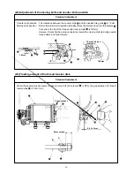
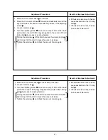
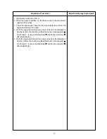
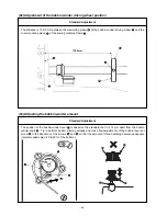
1. Align the Y drive shaft thrust collar
with the flat section of the Y
drive shaft
. Then, tighten two setscrews
.
2. Lightly press the Y drive shaft thrust collar
in Direction A, and also
the Y drive sprocket A
in Direction B. Since then, tighten 2 setscrews
.
At that time, 1 of the setscrews
should be aligned with the flat
section of the Y drive shaft
.
(Caution) Confirm that there is no rattling in axial direction in the
Y drive shaft
.
3. Separate the Y drive sprocket B
by 1mm from the processed face
of the bed and stop it. Then, tighten 2 setscrews
.
At that time, 1 of the setscrews
should be aligned with the flat
section of the Y drive shaft
.
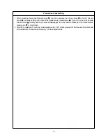
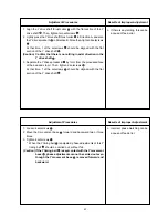
o If there is any rattling, this can be
a cause of feed error.
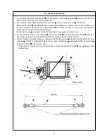
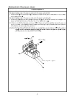
1. Loosen 4 setscrews
.
2. Move the X movement base
forward and backward two or three
times.
3. Tighten 4 setscrews
.
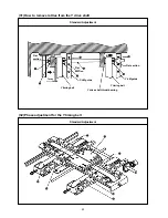
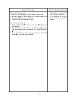
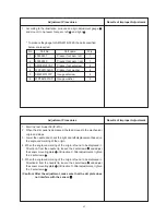
* When the Y timing belt
is adjusted, phase adjustments of this Y
timing belt
should be carried out, without fail.
(Caution) If the Y timing belt
is kept contact with the Y movement
base
, phase adjustments cannot be carried out even
though the Y movement base
is moved forward and
backward.
o Incorrect phase matching can be
a cause of feed error.
Adjustment Procedures
Results of Improper Adjustment
Adjustment Procedures
Results of Improper Adjustment
Содержание AMS-221EHL
Страница 185: ... 181 A JUKI Grease A B JUKI Grease B C Grease A A A A A A A B C C B B B B o MAIN SHAFT NEEDLE BAR COMPONENTS ...
Страница 190: ... 186 o X Y COMPONENTS 1 E C C C C C Grease E Three Bond 3060G Locktight 241 ...
Страница 191: ... 187 o X Y COMPONENTS 2 D D C C C D C C D C Grease D Grease D Locktight 241 ...
Страница 192: ... 188 C Grease D Grease D D C D C C D C D D C C D D D D D C D C o CLOTH FEED MECHANISM COMPONENTS D ...
Страница 231: ... 7 MAIN PANEL board circuit diagram 227 PANEL BOARD MAIN BOARD ...


