1.1.3 Operating instructions µC3 (YLCA / YLHA 100, 120 and 150)
This is a specially programmed controller for air-water coolers and heat pumps with four capacity stages.
These are divided into two independent cooling circuits equipped with two tandems that act upon a
common water circuit. Both systems are equipped with two fans each, the speed of which is controlled
by pressure sensors. The controller operates through the following intakes and outlets.
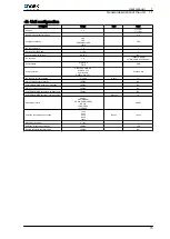
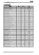
Digital inputs
ID1 ‑ J1/8
General protection (PG)
ID2 ‑ J1/1
Flow switch (FS)
ID3 ‑ J1/9
Remote ON/OFF (ROO)
ID4 ‑ J1/2
Pump protector No. 1 (Q5)
ID5 ‑ J1/10
Low-pressure switch circuit 1 (LP1)
ID6 ‑ J4/8
High-pressure switch circuit 1 (HP1)
ID7 ‑ J4/1
Thermal protector compressor 1 (THPC1)
ID8 ‑ J4/9
Thermal protector compressor 2 (THPC2)
ID9 ‑ J4/2
Thermal protector circuit 1 fans (THPF 1-2)
ID10 ‑ J4/10
Low-pressure switch circuit 2 (LP2)
ID11 ‑ J7/6
High-pressure switch circuit 2 (HP2)
ID12 ‑ J7/1
Thermal protector compressor 3 (THPC3)
ID13 ‑ J7/8
Thermal protector compressor 4 (THPC4)
ID14 ‑ J7/3
Thermal protector circuit 2 fans (THPF 3-4)
ID15 ‑ J7/9
Remote COOL/HEAT (RCH)
ID18 ‑ J7/5
Pump protector No. 2 (Q6)
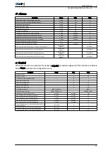
Digital outputs
N01/C1-2
Compressor 1 circuit 1 (K1)
N02/C1-2
Compressor 2 circuit 1 (K2)
N05/C5
Pump 1
N06/C6-7
Compressor 3 circuit 2 (K3)
N07/C6-7
Compressor 4 circuit 2 (K4)
N08/C8-9
Pump 2
N010/C10
Alarm
N011/C11-12
Antifreeze heater circuit 1-2
N012/C11-12
Back-up heater
N013/C13-14
4-way valve circuit 1 (V4V1)
N014/C13-14
4-way valve circuit 2 (V4V2)
User manual
1
General description of the unit
1.1
7


