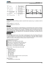
Analogue inputs
B3 ‑ J2
Coil pressure circuit 1
B4 ‑ J3
Coil pressure circuit 2
B5 ‑ J4/13
Water temperature at exchanger inlet
B6 ‑ J4/12
Water temperature at exchanger outlet
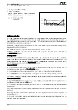
Analogue outputs
Y3
Circuit 1 fan speed control (PWM)
Y4
Circuit 2 fan speed control (PWM)
System components
The system is made up of the following basic components:
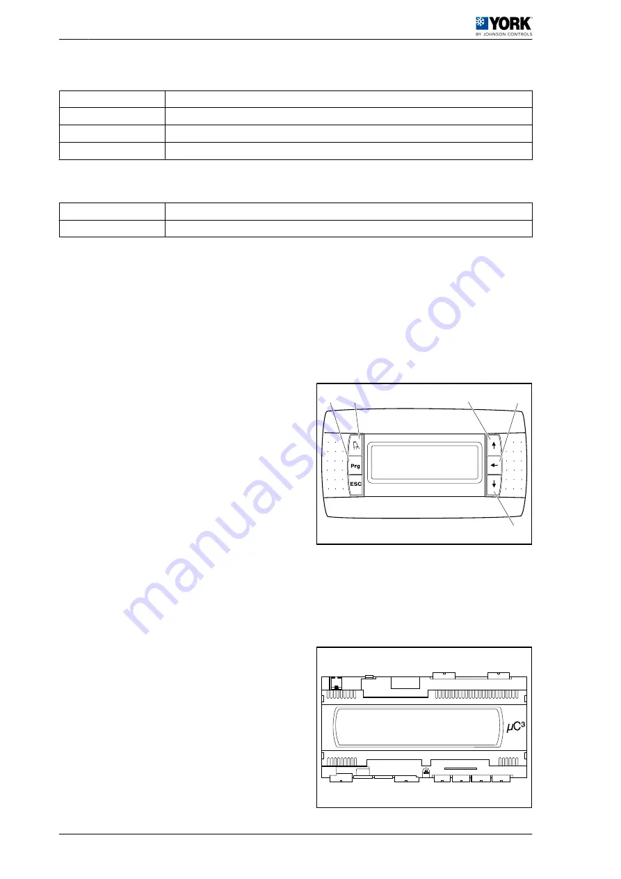
• Touch screen
• µC3 controller
• Fan speed controllers (FSC1 and FSC2)
• Pressure sensors (B3 and B4)
• NTC probes (B5 and B6)
Touch screen
This consists of a screen and six keys with the
following functions:
• Alarm ‑2-
• Programming ‑1-
• Esc (Escape)
• Up ‑3-
• Enter ‑4-
• Down ‑5-
The following functions can be selected from this
screen:
• ON/OFF
• COLD/HEAT
• Read the unit status
• Access the configuration menus (by means of a password)
• Read the alarm messages and reset these alarms
• Read operating pressures and temperatures
• etc...
µC3 controller
This contains the unit software and the entire digital
and analogue input and output connector system.
This module is also equipped with connectors for the
program download key and the serial communication
connection to an RS-485 monitoring system.
1
22
44
33
5
1
User manual
1.1
General description of the unit
8


