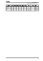
General diagram, (YLCA / YLHA 100,120 and 150)
Q
R
S
A
B
T
M
U
V
A1
C1
E1 F1 G1
H1
J1
B1
D1
D
E
H
K
C
J
I
O
P2
Y
X
A1
Z
M1
K1
P1
O1
A
Keyboard ‑ display terminal
U
Water outlet
B
Programme download key
V
Water inlet
D/J/C/I
Comp. 1/ Comp. 2 / Comp. 3 / Comp. 4
X
Fan protection 1–2
E/H
Pump 1/ Pump 2
Y/A1/G1/
I1
Protection comp. 1 / Protection comp. 2 / Protec‐
tion comp. 3 / Protection comp. 4
K
RS-485 serial connection
Z/H1
HP1 / HP2 (High-pressure switch)
L
Phase (board power supply)
C1
Fan 3.4
M
General protection
D1
Fan 1.2
N
Neutral (board power supply)
F1
Fan protection 3.4
O
Remote ON / OFF
J1
Remote COOL / HEAT
P2/B1
LP1 / LP2 (Low-pressure switch)
K1
Four-way valve, circuit 1
Q/E1
Pump 1 protection / Pump 2 protection
M1
Four-way valve, circuit 2
R
Flow switch
O1
Antifreeze heater
S/T
Circuit 1 pressure sensor / Circuit 2 pressure sensor
P1
Back-up heater
1
User manual
1.1
General description of the unit
10


