background image

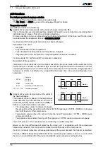
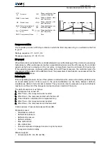
• 4-way valves (N13 and N14)
• Fans (Y3 and Y4)

DefrOff Defrost end pressure

DefrAct Defrost active

DefrOn Defrost start pressure

t

Time

Δt 1...3

Partial  times  remain‐

ing  in  defrost  start

pressure zone


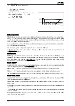
Antifreeze protection
If the B6 temperature sensor (water outlet) detects a temperature below the antifreeze set temperature,

the unit is blocked and in a state of alarm (manual reset). Simultaneously, the protecting heaters of the

plate heat exchanger (output N11) are connected. If the unit includes a hydro kit, the accumulator tank

protection heaters will also be activated.
Said heaters will turn off when the D6 sensor detects a temperature equal to the antifreeze temperature,

plus a preestablished differential.
The antifreeze system will operate despite the status and mode of the unit.
Antifreeze  protection  can  also  include  start-up  of  the  pump  and  unit  (see  parameters  in

theANTIFREEZE menu).
Back-up heater
If following a preestablished time period after unit start-up in heat mode the water outlet temperature

detected by B6 does not reach the minimum value, backup heater output (N12) is activated. Once the

water  temperature  has  reached  said  value,  plus  a  preestablished  differential,  said  output  will  be

deactivated (see parameters in the ANTIFREEZE menu).
Remote ON/OFF
A  digital  ON/OFF  remote  input  can  be  installed  between  terminals  ID3-G0,  and  enabled  with  the

corresponding parameters of the H – unit config menu.
If the contact is open, the unit will remain OFF. If the contact is closed, the unit will remain ON.
If the unit is OFF due to said digital input, a message appears on the display indicating as such.
The unit will remain OFF whenever any of its inputs: user keyboard, digital or monitoring input are OFF.
Remote COOL / HEAT
A digital COOL/HEAT remote input can be installed between terminals ID15-G0, and enabled with the

corresponding parameters of the H menu.
If the contact is open, the unit will remain in HEAT cycle. If the contact is closed, the unit will remain in

COOL cycle.
If the digital COOL/HEAT input is enabled, said selection cannot be made from the user's or supervisor's

keyboard.
To change the cycle, either from the digital input, the user's keyboard or the supervisor's keyboard, the

unit must be OFF.
If the digital COOL/HEAT input is not enabled, said function can be carried out indifferently from the

user's or supervisor's keyboard.

1

User manual

1.1

General description of the unit

20

Содержание YORK YLCA 100

Страница 1: ...Air condensed water chillers and heat pumps YLCA YLHA 100 120 and 150 User manual Ref N 40291_EN 0112...

Страница 2: ...cription of the unit 2 1 1 1 Models available and capacities 2 1 1 2 Technical specifications 4 1 1 3 Operating instructions C3 YLCA YLHA 100 120 and 150 7 1 1 4 Regular maintenance activities for whi...

Страница 3: ...1 User manual...

Страница 4: ...Cool only model YLCA 40 YLCA 50 YLCA 60 YLCA 80 YLCA 100 YLCA 120 YLCA 150 Cooling ca pacity 1 39 3 51 8 60 1 72 1 100 3 118 5 150 5 Cooling ca pacity 2 39 6 52 1 60 5 72 6 101 119 151 1 Net cooling...

Страница 5: ...User manual 1 General description of the unit 1 1 3...

Страница 6: ...panded within the fin assembly Fans Of the axial and low sound level type Equipped with single phase motors with IP54 protection These motors allow speed control by means of a phase cut out shifter co...

Страница 7: ...program models 100 120 and 150 Water filter Supplied as a standard element on units including the hydro kit Stainless steel mesh with 1 mm diameter perforations Optional on units not including the hyd...

Страница 8: ...d and dimensioned in accordance with the load to be supported The antivibratory support accessory for models YLCA YLHA 40 50 and 60 includes 4 units whereas for models YLCA YLHA 80 100 120 and 150 inc...

Страница 9: ...uit 1 HP1 ID7 J4 1 Thermal protector compressor 1 THPC1 ID8 J4 9 Thermal protector compressor 2 THPC2 ID9 J4 2 Thermal protector circuit 1 fans THPF 1 2 ID10 J4 10 Low pressure switch circuit 2 LP2 ID...

Страница 10: ...screen and six keys with the following functions Alarm 2 Programming 1 Esc Escape Up 3 Enter 4 Down 5 The following functions can be selected from this screen ON OFF COLD HEAT Read the unit status Acc...

Страница 11: ...and lockout functions of the system by excessively high pressure NTC probes B5 and B6 B5 For the detection and control of water inlet temperature cool only and heat pump units B6 For the detection of...

Страница 12: ...ion comp 3 Protection comp 4 K RS 485 serial connection Z H1 HP1 HP2 High pressure switch L Phase board power supply C1 Fan 3 4 M General protection D1 Fan 1 2 N Neutral board power supply F1 Fan prot...

Страница 13: ...ssword display press ENTER 2 Enter the password using the Up key 3 Press ENTER to access the 4th Menu display 4th display MENU From this display we can access a set of submenus that provide informatio...

Страница 14: ...0 bar 0 Probe B3 configuration Maximum value 30 151 bar 45 Probe B4 configuration Minimum value 30 152 bar 0 Probe B4 configuration Maximum value 30 153 bar 45 A Antifreeze Description Range Units Val...

Страница 15: ...hours for compressor 2 circuit 2 maintenance alarm 1000 999000 Hours 0 x 1000 Tandem compressor rotation time Minutes 20 Enabling of compressors C1 1 C2 1 C1 2 C2 2 YES NO YES Forced manual compresso...

Страница 16: ...orating pressure differential in summer cycle 0 99 9 bar 1 5 Min fan speed differential 99 9 99 9 bar 3 Max inverter speed 0 10 V 10 Min inverter speed 0 10 V 1 Inverter speed up time 0 999 Seconds 5...

Страница 17: ...ALWAYS ON No of hours for pump rotation 0 9999 Hours 12 ON OFF digital input activation YES NO NO WINTER SUMMER digital input activation YES NO NO ON OFF activation with Monitor YES NO NO WINTER SUMM...

Страница 18: ...ure switch circuit 2 O C 0 OPEN C CLOSED Digital input 12 Thermal protector compressor 3 circuit 2 O C 0 OPEN C CLOSED Digital input 13 Thermal protector compressor 4 circuit 2 O C 0 OPEN C CLOSED Dig...

Страница 19: ...Alarm selection with automatic reset high pressure switch AUTOMATIC MANUAL AUTOMATIC r Control When this submenu is activated the dynamic set point temperature appears if this function is enabled Pres...

Страница 20: ...behaviour is similar but affected by al algorithm that takes time into account integration time parameter STPM Set point A Cool B Heat RBM Control band EWT Exchanger inlet temperature C1 C2 C3 C4 Comp...

Страница 21: ...ff a compressor in the tandem of the affected circuit The parameters of said function are accessed from the CONDENSATION menu Defrost cycle If the evaporating pressure of one of the systems remains be...

Страница 22: ...water temperature has reached said value plus a preestablished differential said output will be deactivated see parameters in the ANTIFREEZE menu Remote ON OFF A digital ON OFF remote input can be in...

Страница 23: ...e this function from the H unit config menu The system has two monitoring protocols Carel and Modbus AUTO RESTART When the unit is turned off by a power shortage and once this has been restored the un...

Страница 24: ...h fault within 60 interval man ual reset Compressor 3 A3 heat switches YCSA LCA 150 YCSA H BRAW 150 ID12 Comp 3 AUTO MANUAL 5th fault within 60 interval automatic reset 5th fault within 60 interval ma...

Страница 25: ...an Off pump Off sys Reset Delay Notes maintenance Compressor 4 maintenance System MANUAL Set period in Compressor menu No link Display CHECK CABLE CONFIGURE No MCH3 com munication and display User man...

Страница 26: ...12 16 55 46 4 74 80 1 66 21 71 07 13 15 9 47 4 59 81 1 62 20 67 74 14 15 28 48 4 44 82 1 57 19 64 54 15 14 68 49 4 3 83 1 53 18 61 62 16 14 12 50 4 16 84 1 49 17 58 66 17 13 57 51 4 02 85 1 45 1 1 4...

Страница 27: ...d safety regulations and procedures applicable to HVAC units They should also be aware of general procedures and those applying specifically to this unit Contact a Johnson Controls Inc Authorised Tech...

Отзывы: