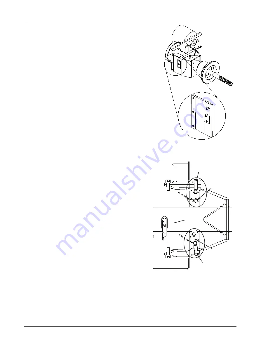
Set
Screw
Rear
Transducer
Rear
Transducer
Set
Screw
Encoder
Checkout and maintenance
1-18
TRANsDUCER REMOVAL
• The transducers are held in place with setscrews and jam
nuts.
• Disconnect the power from the rear of the machine.
• Remove the display panel.
• Remove the weight tray.
• using a 2.5mm hex key remove the preload plate. (Figure
3-26)
• using a 13mm wrench loosen the jam nut.
• using a 5mm hex key, back the set screw off by turning
counterclockwise. Do not lose the ball bearings on each end
of the tranducers. These allow the transducer to center easily
on the vibratory member.
• If the transducer is being replaced using a marker mark the
front and rear transducer harnesses. Cut the two wires at the
transducer. The positive lead of the harness is marked with a
black band. (When using a harness and transducer assem
-
bly, this step is unnecessary.)
INsTALLATION OF TRANsDUCER
• The front and rear transducer must be installed correctly
in order for the balancer to function correctly. The rear
transducer uses the last 2 wires pins 15-16 in the har
-
ness.
• Connect the positive and negative lead to the transducer.
The positive lead is marked with a black band.
• Insert the clip into the transducer firmly snapping it into
place. Once the wire is installed it cannot be removed
without destroying the transducer.
• Apply a small amount of grease to each end of the trans
-
ducer. Place the ball bearings in place on the transducer.
Place the transducer assembly in the vibratory system.
• Finger tighten the set screw to position the transducer.
The wire connection should be on the bottom. A properly
installed transducer will be able to rotate freely but must
have no side to side motion.
• Snug the jam nut that holds the setscrew. This nut
should be tightened solidly, but need not be extremely
tight. Recheck the transducer to ensure that no lateral
movement exists after tightening the jam nut. Adjust as
necessary.
• Hold the pre-load plate in position up to the jam nut and finger tighten the set screws to just hold
the plate in place without movement. Tighten the upper screw ½ turn, then tighten the lower screw one
full turn, then tighten the upper screw an additional ½ turn.
• Reassemble the complete balancer and perform a complete factory calibration to ensure proper opera
-
tion.
NOTE: MOVING THE TRANSDUCER AFTER CALIBRATION WILL CHANGE THE ACCURACY AND
REQUIRE FACTORY CALIBRATION
Содержание EEWB304B
Страница 1: ...WHEEL BALANCER Service Manual EEWB502B C EEWB503B EEWB304B ...
Страница 56: ......


