16021730 Rev. 0
34
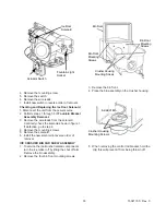
Control Rod
Control Rod
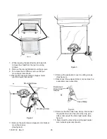
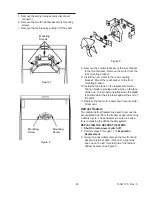
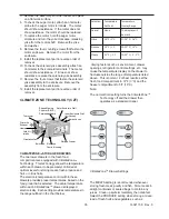
6. When removing the crusher housing, position the
snap ring (1) as shown in the drawing below, then
remove it and the retainer washer (2).
7. Push the auger assembly away from the crusher
housing using your thumb (3).
Crusher Blades
Fixed Blades
Auger Nut
8. To remove the auger nut turn it clockwise.
9. Replace the parts required. The number on
the blades should face the back of the auger
nut. Blade number 4 should be nearest to the
auger nut.
10. Reinstall all other components in the reverse
order of removal.
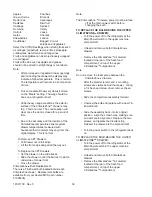
ICE/CRUSHER BIN SHELF
ENCLOSURE ASSEMBLY
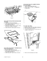
Yoke / Solenoid
Mounting
Auger Motor
Mounting
The auger motor and solenoid are located behind
the storage bin. The yoke, fastened to the motor,
engages the drive ring and turns auger in a
clockwise direction. Both the yoke and drive ring
are designed to prevent a loosening of the yoke
by exerting counter pressure while in operation.
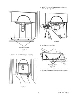
1.
Disconnect the unit from the power
source.
2. Remove the ice/crusher bin assembly.
3. Remove the retainer screw at the bottom left
side of the ice/crusher bin shelf enclosure.
4. Pull the shelf forward and disconnect the quick
disconnect.
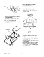
Auger
Yoke / Solenoid
Содержание Luxury Series
Страница 13: ...13 16021730 Rev 0 Refrigerant Flow Side by Side Refrigerant Flow Diagram ...
Страница 14: ...16021730 Rev 0 14 Cabinet Air Flow Side by Side Cabinet Air Flow Diagram ...
Страница 16: ...16021730 Rev 0 16 Water Valves Diagram Bottom View Back View Primary Valve Secondary Valve Filter Head Bypass ...
Страница 46: ...A 1 ...
Страница 72: ...B 1 Appendix B ...

