16021730 Rev. 0
8
Open Lines
During any processing of refrigeration system, never
leave lines open to atmosphere. Open lines allow water
vapor to enter system, making proper evacuation more
difficult.
Dehydrating Sealed Refrigeration System
Moisture in a refrigerator sealed system exposed to
heat generated by the compressor and motor reacts
chemically with refrigerant and oil in the system and
forms corrosive hydrochloric and hydrofluoric acids.
These acids contribute to breakdown of motor winding
insulation and corrosion of compressor working parts,
causing compressor failure.
In addition, sludge, a residue of the chemical reaction,
coats all surfaces of sealed system, and will
eventually restrict refrigerant flow through capillary
tube.
To dehydrate sealed system, evacuate system (see
paragraph
Evacuation
).
Leak Testing
DANGER
!
To avoid risk of serious injury or death from violent
explosions, NEVER use oxygen or acetylene for
pressure testing or clean out of refrigeration
systems. Free oxygen will explode on contact with
oil. Acetylene will explode spontaneously when put
under pressure.
It is important to check sealed system for refrigerant
leaks. Undetected leaks can lead to repeated service
calls and eventually result in system contamination,
restrictions, and premature compressor failure.
Refrigerant leaks are best detected with halide or
electronic leak detectors.
Testing Systems Containing a Refrigerant Charge
1. Stop unit operation (turn refrigerator off).
2. Holding leak detector exploring tube as close to
system tubing as possible, check all piping, joints,
and fittings.
NOTE
: Use soap suds on areas leak detector cannot
reach or reliably test.
Service Procedures
To avoid risk of electrical shock, personal injury, or death, disconnect electrical power source to unit, unless test
procedures require power to be connected. Discharge capacitor through a 10,000 ohm resistor before attempting
to service. Ensure all ground wires are connected before certifying unit as repaired and/or operational.
!
WARNING
Testing Systems Containing No Refrigerant Charge
1. Connect cylinder of nitrogen, through gauge
manifold, to process tube of compressor and liquid line
strainer.
2. Open valves on nitrogen cylinder and gauge manifold.
Allow pressure to build within sealed system.
3. Check for leaks using soap suds.
If a leak is detected in a joint, do not to attempt to repair
by applying additional brazing material. Joint must be
disassembled, cleaned and rebrazed. Capture refrigerant
charge (if system is charged), unbraze joint, clean
allparts, then rebraze.
If leak is detected in tubing, replace tubing. If leak is
detected in either coil, replace faulty coil.
Restrictions
Symptoms
Restrictions in sealed system most often occur at
capillary tube or filter drier, but can exist anywhere on
liquid side of system.
Restrictions reduce refrigerant flow rate and heat
removal rate. Wattage drops because compressor is
not circulating normal amount of refrigerants.
Common causes of total restrictions are moisture,
poorly soldered joints, or solid contaminants. Moisture
freezes at evaporator inlet end of capillary tube. Solid
contaminants collect in filter drier.
If restriction is on low side, suction pressure will be in a
vacuum and head pressure will be near normal.
If restriction is on high side, suction pressure will be in
a vacuum and head pressure will be higher than normal
during pump out cycle.
Refrigeration occurs on low pressure side of partial
restriction. There will be a temperature difference at the
point of restriction. Frost and/or condensation will be
present in most case at the point of restriction. Also,
system requires longer to equalize.
Slight or partial restriction can give the same
symptoms as refrigerant shortage including lower than
normal back pressure, head pressure, wattage, and
warmer temperatures.
Total restriction on the discharge side of compressor,
when restriction is between compressor and first half of
condenser, results in higher than normal head pressure
and wattage while low side is being pumped out.
Содержание Luxury Series
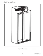
Страница 13: ...13 16021730 Rev 0 Refrigerant Flow Side by Side Refrigerant Flow Diagram ...
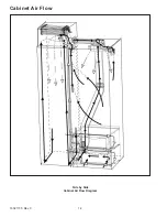
Страница 14: ...16021730 Rev 0 14 Cabinet Air Flow Side by Side Cabinet Air Flow Diagram ...
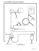
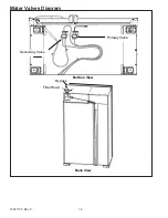
Страница 16: ...16021730 Rev 0 16 Water Valves Diagram Bottom View Back View Primary Valve Secondary Valve Filter Head Bypass ...
Страница 46: ...A 1 ...
Страница 72: ...B 1 Appendix B ...


