3
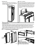
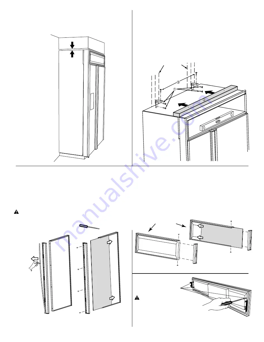
Blocking the Unit:
If there is a solid soffit above the unit and the clearance is 1"
or less you will not need to block the unit. For installations with
clearances of more than 1", you must use the anti-tipping 2x4
and brackets provided (Fig. 6).
More than
an 1"
Soffit
Fig. 7
More than 1" clearance:
Use the anti-tipping kit provided with the shipping crate. Locate and
mark the 2 wall studs behind the unit. Mark where the "L" brackets
and 2x4 will be located and drill 2 pilot holes 1/8". Locate the proper
height to clear the unit. The space between the top of the unit and
bottom of the wood block must not exceed 1/4". Secure the "L"
brackets, using the provided screws, into the wall studs
(
À
)
.
Make
sure the screws will extend 7/8" into the wall studs. Align the pilot
holes with the "L" brackets and secure the 2x4 with the screws
provided(
Á
,
Â
)
.
Wall Studs
Installing Backer Panels:
Remove the door handle or trim piece on overlay models. A magnetic backed molding hides the handle or overlay trim screws. Use the
adhesive side of the packaging tape on the magnetic backed molding to pull it away from door (Fig. 8a). Remove the screws with a
phillips screwdriver (Fig. 8b). Slide the backer panel into position. The backer panel needs to be under the trim. Install the handle.
Replace the molding in the channel, and reset the magnetic backed molding. To install the backer panel on the grille remove the screws
on the top and bottom of the upper cover (Fig 8c). DO NOT REMOVE the foam. Slide the backer panel into place and replace screws
(Fig 8d). If the thickness of the backer panel is less than a 1/4", back it up with a sheet of shim material to obtain a 1/4" thickness.
Cardboard is recommended for Stainless Steel application.
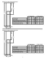
For panel size refer to Fig. 10.
Fig. 8a
Fig. 8b
Fig. 8d
Grille Panel
Fig. 8c
CAUTION:
Do not drive screws or sharp objects into the doors.
Do not pinch door seal when reinstalling handle.
Phillips Screwdriver
Use Tape
to Pull Magnetic
Molding Away
from Door
Approximate Position
For Screws
CAUTION:
When attaching a raised wood
panel of 1/2" or thicker secure the
raised panel to the back of the grille
cover frame. Use 4 #8 or similar screws.
See illustration for approximate locations.
Fig. 6
Содержание Luxury Series
Страница 13: ...13 16021730 Rev 0 Refrigerant Flow Side by Side Refrigerant Flow Diagram ...
Страница 14: ...16021730 Rev 0 14 Cabinet Air Flow Side by Side Cabinet Air Flow Diagram ...
Страница 16: ...16021730 Rev 0 16 Water Valves Diagram Bottom View Back View Primary Valve Secondary Valve Filter Head Bypass ...
Страница 46: ...A 1 ...
Страница 72: ...B 1 Appendix B ...

