27 16021730 Rev. 0
HEAT EXCHANGER REPLACEMENT
1. Follow steps one thru three on compressor
replacement.
2. Unsolder the suction line from the suction stub
of the compressor.
3. Unsolder the other end of the suction line from
the evaporator.
4. Unsolder the capillary tube at the muffler.
5. Remove and replace the old drier from the yoder
loop.
6. Remove the old heat exchanger.
7. Make an offset 1/2" from the end of the capillary
tube and insert it into the new drier.
8. Install the new heat exchanger assembly in
reverse order of removal.
9. Sweep and recharge the unit.
10. Test for leaks.
11. Install the machine compartment cover.
12. Test run the refrigerator to make sure
it is operating properly.
ELECTRICAL SYSTEM
The wiring diagram is located in the machine
compartment area.
All electrical components are grounded to the
cabinet.
The green/yellow center conductor in the power
cord is attached to the cabinet to provide a ground
circuit when the cord is plugged into a properly
grounded outlet.
After replacing an electrical component,
always
reconnect the ground wire.
The electrical outlet should be checked to make
sure it is properly wired. Check the outlet with a
circuit tester.
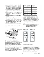
The Compressor
The compressor is a variable speed compressor.
The starting and run speeds are controlled by the
compressor PC board. The compressor terminals
resistance are of equal value. Placing ohm meter
probes on any two terminals of the compressor
should read the same.
Note: There are no overload protector or starting
relay on the terminals of the compressor
every thing is controlled on the PC board.
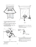
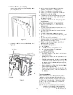
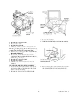
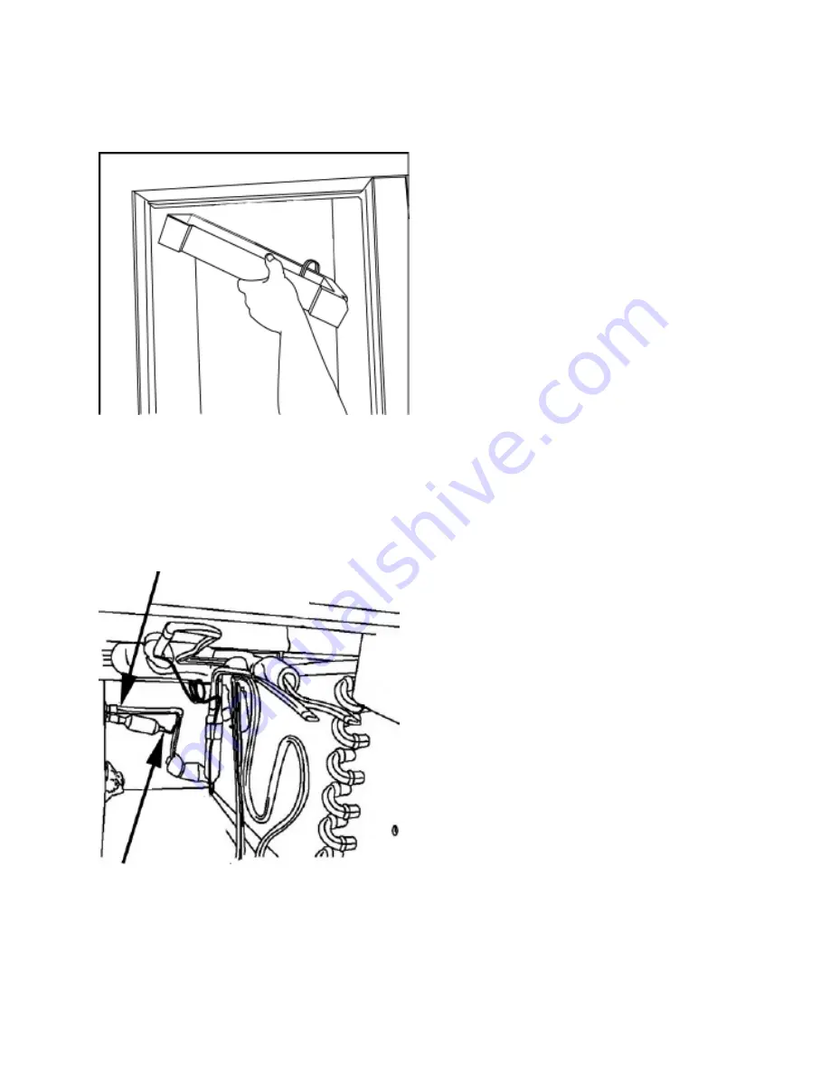
16.Remove the drip pan assembly.
order of removal and all other parts that were
previously removed.
Figure 5
17. Carefully lower the drain pan assembly. (See
figure 5).
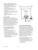
Cut Line
Cut Line
Figure 6
18.Cut the suction line and the cap tube in the
machine compartment. (See figure 6).
19.Remove the evaporator mounting screw.
20.Remove the evaporator assembly transfer the
heaters to the new assembly.
21.Install the new evaporator assembly in reverse
order of removal and all other parts that were
previously removed.
22. Change the drier. Evacuate and recharge and
test the system.
Содержание Luxury Series
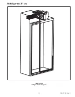
Страница 13: ...13 16021730 Rev 0 Refrigerant Flow Side by Side Refrigerant Flow Diagram ...
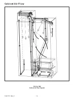
Страница 14: ...16021730 Rev 0 14 Cabinet Air Flow Side by Side Cabinet Air Flow Diagram ...
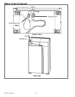
Страница 16: ...16021730 Rev 0 16 Water Valves Diagram Bottom View Back View Primary Valve Secondary Valve Filter Head Bypass ...
Страница 46: ...A 1 ...
Страница 72: ...B 1 Appendix B ...

