16021730 Rev. 0
32
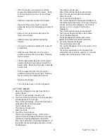
9. Install the new PC board/frame assembly in
reverse order of removal.
Touch Fountain Assembly Removal
1.
Shut the main power switch off.
2. Perform steps 1 through 7 of
the PC Board/
Frame Removal.
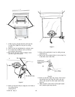
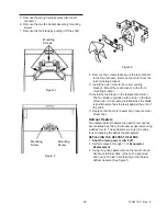
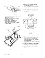
Figure 1
Mounting Screws
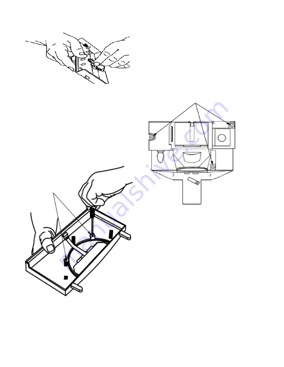
3.Remove the two touch fountain assembly
mounting screws (figure 1).
4. Remove the old assembly and install the new
assembly in reverse order of removal.
Fountain Bracket Assembly Removal
1.
Shut the main power switch off.
2. Perform steps 1 through 7 of the
PC Board
Frame Removal.
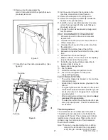
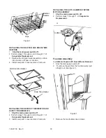
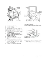
Figure 1
Fountain Bracket
Mounting Screws
3. Remove the three fountain bracket mounting
screws.
4. Carefully pull the assembly out of the fountain
housing. You now have full access to the
solenoid, dispenser mechanism, light socket
and the actuator switch.
5. To repair the assembly , disconnect the electrical
quick disconnect.
Checking and Replacing the Actuator Switch:
1. Disconnect the unit from the power Source.
2. Perform steps 1 through 5 of
Fountain Bracket
Assembly Removal.
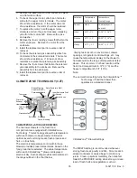
3. Continuity check the actuator switch shown in
figure 1.
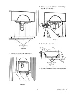
F i g u r e 6
8. Disconnect the electrical lead from the fountain
PC board/frame assembly.
Содержание Luxury Series
Страница 13: ...13 16021730 Rev 0 Refrigerant Flow Side by Side Refrigerant Flow Diagram ...
Страница 14: ...16021730 Rev 0 14 Cabinet Air Flow Side by Side Cabinet Air Flow Diagram ...
Страница 16: ...16021730 Rev 0 16 Water Valves Diagram Bottom View Back View Primary Valve Secondary Valve Filter Head Bypass ...
Страница 46: ...A 1 ...
Страница 72: ...B 1 Appendix B ...

