10 - 7
Section F
Transmission
9803/6410
Section F
10 - 7
Issue 1
Reduction Gear - JS160
Assembly (cont’d)
When Assembling (cont’d)
4
Completely degrease the threaded holes of spindle 2
and then apply thread adhesive. Also degrease bolts 35
and then apply an anti-seize coating beneath the bolt
head.
5
If renewing the inner races of bearings 149 and 150,
pre-heat to 100 ± 10 °C (212 ± 18 °F) and install using
press tool B (see Service Tools, Section 1) as shown.
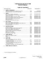
6
Before installing the carrier 3 assembly, set-up the
cluster gears 6 with matching marks (positions C as
shown). Insert sun assembly tool (see Service Tools,
Section 1) to lock the gears relative to each other. Install
the carrier into ring gear 5 and then install the ring gear
assembly into hub 1. Remove the sun gear assembly
tool.
7
Accurate positioning of ring gear 4 relative to hub 1 is
essential. Degrease the two surfaces where the ring
gear contacts the hub and apply a light coat of liquid
gasket. Install ring gear 4 into hub 1, taking care to
mesh the teeth of the ring gear with those of cluster
gears 6. Rotate the ring gear so that its match mark D
aligns with the match mark of hub 1, as shown opposite.
JS00640
JS00650
JS00610
Содержание JS130
Страница 39: ...3 3 Section 3 Routine Maintenance 9803 6410 Section 3 3 3 Issue 1 Greasing continued Excavator End...
Страница 65: ...Section 3 Section 3 9803 6410 Issue 1 9 1 9 1 Routine Maintenance Component Location Diagram...
Страница 118: ......
Страница 119: ...3 1 Section C Electrics 9803 6410 Section C 3 1 Issue 1 Layout Operator s Cab...
Страница 142: ...5 3 Section C Electrics 9803 6410 Section C 5 3 Issue 1 Pump Control FLOW CHART...
Страница 145: ...5 6 Section C Electrics 9803 6410 Section C 5 6 Issue 1 Pump Control Cushioned Boom Starting continued Flow Chart...
Страница 148: ...5 9 Section C Electrics 9803 6410 Section C 5 9 Issue 1 Pump Control Pressure Increasing System continued Flow Chart...
Страница 155: ...5 16 Section C Electrics 9803 6410 Section C 5 16 Issue 1 Pump Control Power Supply Cut Delay Flow Chart...
Страница 159: ...5 20 Section C Electrics 9803 6410 Section C 5 20 Issue 1 Pump Control Swing brake Swing lock continued Flow Chart...
Страница 160: ...5 21 Section C Electrics 9803 6410 Section C 5 21 Issue 1 Pump Control Lever Lock Circuit Diagram Time Chart...
Страница 161: ...5 22 Section C Electrics 9803 6410 Section C 5 22 Issue 1 Pump Control Lever Lock continued Flow Chart...
Страница 207: ......
Страница 209: ......
Страница 210: ...3 4 Section E Hydraulics 9803 6410 Section E 3 4 Issue 2 Schematics Shuttle Block...
Страница 211: ...Section E Section E Hydraulics 9803 6410 Issue 2 3 5 3 5 Schematics Pilot Control Line Hose Connection Diagram JS03540...
Страница 212: ...Section E Section E Hydraulics 9803 6410 Issue 1 3 6 3 6 Schematics Pilot Control Line Hose Connection Diagram JS03540...
Страница 234: ...14 1 Section E Hydraulics 9803 6410 Section E 14 1 Issue 1 JS00010 Hydraulic Pump Regulator Dismantling and Assembly...
Страница 278: ...32 2 Hydraulic Circuit Diagram Section E Hydraulics 9803 6410 Section E 32 2 Issue 1 Control Valve JS01700...
Страница 279: ...33 1 Neutral Circuit Section E Hydraulics 9803 6410 Section E 33 1 Issue 1 Control Valve JS01610...
Страница 284: ...33 6 Boom Raise BM Operation Section E Hydraulics 9803 6410 Section E 33 6 Issue 1 Control Valve L...
Страница 287: ...33 9 Slew Operation SW Priority Circuit Section E Hydraulics 9803 6410 Section E 33 9 Issue 1 Control Valve JS01770...
Страница 293: ...Hydraulics 9803 6410 Issue 1 34 3 34 3 Section E Section E Control Valve JS01820 Dismantling and Assembly cont d...
Страница 532: ...Contents Page No Technical Data 1 1 i Engine 9803 6410 i Issue 1 Section K Section K...