background image

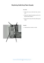
(A)

(B)

Replacing Switching Power Supply

To remove:

1. Remove the top cover, belt cover, base, and rear

cover.

2. Remove the screws (A) and (B), and remove the

switching power supply (1).

3. Disconnect harness (2) from the switching power

supply.

To attach:

4. Follow the above procedure in reverse.

(1)

(2)

15

www.promelectroavtomat.ru

Содержание MC 11000 -

Страница 1: ...SERVICE MANUAL MC11000 www promelectroavtomat ru...

Страница 2: ...Position and Height 22 Feed dog height 23 Height of Embroidery Foot P 24 Shield Plate Position 25 Tension Release Mechanism 26 Needle Thread Tension 27 Replacing and Adjusting Threader plate 28 Adjust...

Страница 3: ...aise the carrying handle 3 and remove the screw D 3 Raise the top cover and disconnect the bobbin winder connector 4 Remove the top cover sliding towards the back Note The pressure dial is removed wit...

Страница 4: ...and their screws B and C 3 While pushig down the stopper 2 under the belt cover remove the belt cover To attach 4 Match the belt cover position with the front cover 5 Attach the belt cover while push...

Страница 5: ...External Parts 3 Replacing the bed cover To remove 1 Remove the extension table 2 Remove the 2 screws A and remove the bed cover To attach 3 Follow the above procedure in reverse A 3 www promelectroav...

Страница 6: ...base push the machine body away from you Do not pull the base toward you To attach 5 Tighten the 4 screws A and B slightly 6 Attach the extension table 7 Match the extension table base and free arm po...

Страница 7: ...emove the screw A and remove the rear arm thread guide 1 3 Loosen the screw B 4 Loosen the screw C and remove the screw D 5 Disconnect each connector and remove the front cover Note Unlock the hooks 2...

Страница 8: ...Remove the top cover belt cover and base 2 Loosen the screws A B and C and remove the screw D 3 Lower the presser foot and remove the rear cover To attach 4 Follow the above procedure in reverse Rear...

Страница 9: ...3 Remove the screws A and B 4 Pull the connector out from the U board and remove the thread tension unit To attach 3 Follow the above procedure in reverse Note After changing the thread tension make s...

Страница 10: ...ead cutter unit check that the driving arm 4 is functioning properly by turning the handwheel 1 Lower the needle bar to its lowest position 2 Push the driving arm 1 down and insert the pin 3 into the...

Страница 11: ...n winding motor and the needle threader sensor from printed circuit board U Note Remove the cords from the cord guide 1 4 Remove the 2 screws B and remove the motor Note Remove the lamp supporter 2 be...

Страница 12: ...ion 1 of the needle bar supporter into the corner part of the moval body 2 6 Attach the motor 4 7 Insert each cord into the cord guide 3 and connect to printed circuit board U Attach the front cover 8...

Страница 13: ...r foot lifter sensor brown P foot sensor blue Printed circuit board A black Printed circuit board L3 gray Printed circuit board A black Needle threader motor black Printed circuit board A LCD detectio...

Страница 14: ...remove 1 Remove the front cover 2 Disconnect each connector from printed circuit board A 3 Remove the 8 screws A and remove printed circuit board A with the card guide 1 To remove 4 Follow the above p...

Страница 15: ...e Printed circuit board F2 To remove 1 Remove the front cover 2 Pull out the connector from printed circuit board A 3 Remove the 3 screws B and remove printed cir cuit board F2 2 To attach 4 Follow th...

Страница 16: ...urn the machine to the back 2 Remove the base 1 3 Remove the 2 screws A and remove printed circuit board B case 2 and circuit board B 3 4 Disconnect the herness 4 from printed circuit board B To attac...

Страница 17: ...ve the top cover belt cover base and rear cover 2 Remove the screws A and B and remove the switching power supply 1 3 Disconnect harness 2 from the switching power supply To attach 4 Follow the above...

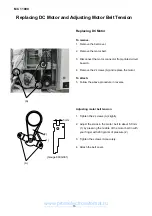
Страница 18: ...move the 2 screws A and replace the motor To attach 5 Follow the above procedure in reverse Adjusting motor belt tension 1 Tighten the 2 screws A slightly 2 Adjust the slack in the motor belt to about...

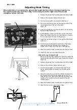
Страница 19: ...ve the top cover and slect stitch No 1 straight stitch Lower the needle to its lowest position by turning the handwheel toward you 2 Loosen the screw A Move the zigzag rod 1 left or right to set the n...

Страница 20: ...lower shaft gear 3 until the tip of the rotary hook meets with the right side of the needle 5 Tighten the 2 screws A of the lower shaft gear 3 9 Attach the bobbin holder needle plate and presser foot...

Страница 21: ...s facing exactly forward 8 Close the face cover 9 Reattach the bobbin holder needle plate and presser foot Alternative way of adjustment 1 Raise the needle to its highest position 2 In this condition...

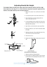
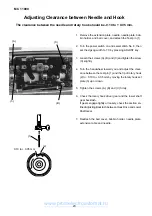
Страница 22: ...C and tighten the screw C slightly 4 Turn the handwheel toward you and adjust the clear ance between the test pin 1 and the tip of rotary hook 2 to 0 10 to 0 05 mm by moving the rotary hook set plate...

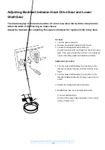
Страница 23: ...Jog the hook race with your fingers to check the rotary play If the play is larger than 0 8 mm or the gears do not turn smoothly adjust the backlash as follows Adjustment procedure 1 Turn the lower s...

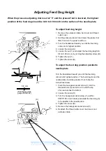
Страница 24: ...he foot and the feed dog window on the needle plate should be parallel 1 Open the face cover 2 Raise the presser foot loosen screw A to adjust the presser foot position and presser foot height then re...

Страница 25: ...rning the adjusting screw B 6 Tighten the nut 1 7 Tighten the screw A To adjust the feed dog position parallel to needle plate Turn the handwheel toward you until the feed dog comes to its highest pos...

Страница 26: ...ition and lower the presser bar lifter 3 Insert a 0 8 mm thickness gauge 1 between the embroidery foot P 2 and the needle plate 3 4 While pressing the presser bar actuator 4 down against the upper sha...

Страница 27: ...the adjusting window 3 Press PHSensor on the touch panel 4 Turn the handwheel toward you and raise the needle between 8 3 and 8 7 mm 1 above the surface of the needle plate 5 Remove the base and loose...

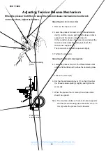
Страница 28: ...disc supporter 5 The tension discs should be opened slightly 3 Tighten the screw A Adjusting the thread releasing plate 4 Lower the presser foot turn the thread tension dial until the flat surface pa...

Страница 29: ...in the direction of the arrow 1 Turn the power switch on and select the stitch No 1 Press the needle up down button twice 2 Set the thread tension to 3 4 by pressing the ADJUST key 3 Lower the presser...

Страница 30: ...the 2 screws A and replace the threader plate 2 To adjust 1 If threader hook 3 thrusts or hits against either the left or right edge of the needle eye Loosen the 2 screws A and adjust the position of...

Страница 31: ...ve the 2 screws A and remove the motor cover 1 2 Loosen the screw B and adjust the position of the switch 2 by moving it up or down so that the needle threader stops with a 3 mm gap 3 between the slid...

Страница 32: ...p Down button 1 turn the power switch on Keep pressing the Needle Up Down button until PRESS MARK and appear 2 Press the mark with astylus or the tip of the additional spool pin Press to in order 3 Wh...

Страница 33: ...en shows the adjusting window 2 Press the 8 Adjust key on the touch panel 3 Set the feed balancing dial 1 at the standard setting mark 2 4 Check the sewing results The standard length of the consecuti...

Страница 34: ...screen shows the adjusting window 2 Press the Foot UD key on the touch panel 3 Remove the top cover 4 Loosen the screw A and adjust switch fixing plate 1 so that the screen shows H when the presser fo...

Страница 35: ...buttonhole lever guide 1 so that the screen shows L when the buttonhole lever 2 is lowered Then tighten screw A 4 Attach the BH foot R and lower the BH lever 2 5 Insert a 1 6 mm thickness gauge 3 betw...

Страница 36: ...nsor shield plate 1 to the left most po sition until it touches the sensor 2 lightly L will ap pear on the touch panel 7 Remove the zigzag foot 3 and lower the presser bar H will appear on the touch p...

Страница 37: ...ey button several times and check if the same number appears each time 4 Press the MEM1 button The data for step 3 should be registered in MEM1 5 Insert the 10 3 mm diameter gauge or wound see below b...

Страница 38: ...mm when the plunger is operated 1 Remove the belt cover and base 2 Loosen the 2 screws A and move the set plate 1 up or down to make the space between the snap ring 2 of the plunger and the upper sur...

Страница 39: ...yoke should be 5 mm 1 Remove the belt cover 2 Loosen the 2 screws A and move the yoke 1 up or down to make a space of 5 mm between the snap ring 2 of the plunger and the upper surface of the yoke 3 Ti...

Страница 40: ...ctuator arm 1 L will be indicated on the Solenoid 2 window of the touch panel If the screen dose not show L loosen screw A and adjust it by moving the switch left or right 6 When raising actuator arm...

Страница 41: ...the stopper in the direction A If tnot enough thread is allowed turn the stopper in the direction B 2 Tighten the setscrew 1 firmly A B Adjusting Bobbin Winder Stopper The amount of thread wound on t...

Страница 42: ...be in the range of 5 45 5 75 mm 1 Remove the needle plate 2 Loosen the hexagonal bolt 1 and adjust the distance of the thread drawing lever 2 from the bobbin holder 3 to be between 5 45 mm and 5 75 m...

Страница 43: ...y base covers 4 and 5 4 Loosen the screw A to adjust dimension Y to be between 16 mm and 17 mm by moving the Y sensor attaching plate 6 5 Loosen the screw B to adjust dimension X to be between 4 3 mm...

Страница 44: ...witch on Select the embroidery mode and select stitch No 1 5 Check if the needle 3 passes through the start posi tion hole 4 of the template 6 Turn the power switch off 7 If there is a gap loosen the...

Страница 45: ...p lever B long E Insert the needle bar crank into the take up crank C so that the flat part of the needle bar crank D faces the long setscrew B Tighten the setscrew B then the short setscrew A A short...

Страница 46: ...uce the play of the declutch slider loosen the set screws F and G While pushing the upper shaft declutch device to the right tighten the setscrew F Then tighten the setscrew G Make sure that the declu...

Страница 47: ...angle of the parts A B and C should be the same as D Setting Position of Parts on Lower Shaft Feed lifting cam Cam B Feed cam C Spring pin D Belt wheel Shield plate Cam A Pin VIEW X VIEW Y VIEW X VIE...

Страница 48: ...pper and Lower Shafts When the setting mark A on the cam B is exactly at the top the spring pin E should be vertical and the setting mark C on the belt wheel D should be in the position as shown A B C...

Отзывы: