background image

11

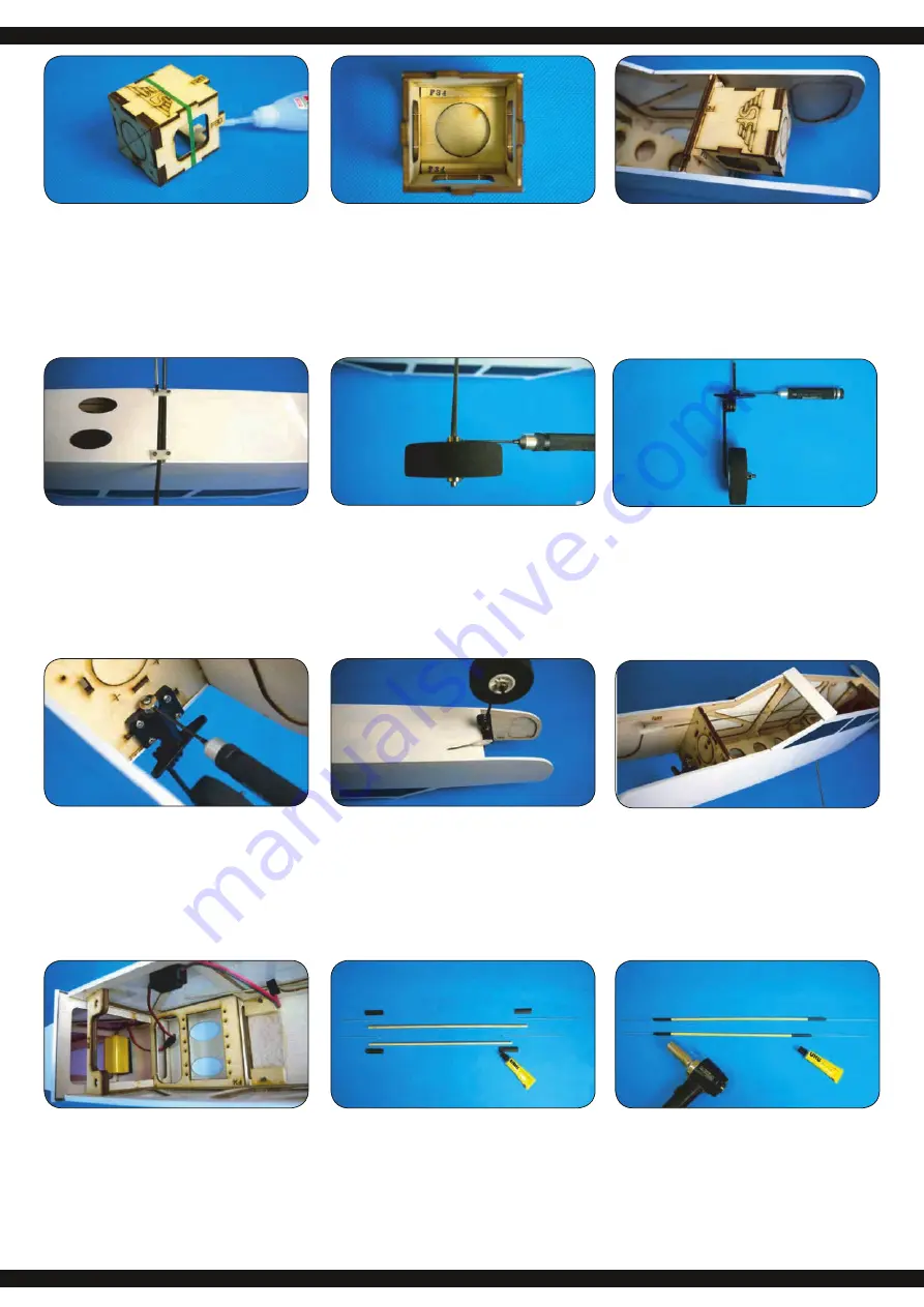
Verkleben Sie die Teile F29 - F33 wie oben gezeigt. 

Use instant glue to secure F29-F33 in place with SF logo facing 

top.

Wenn der Kleber getrocknet ist, bestreichen Sie die Teile F34 mit 

Klebstoff und kleben Sie diese zur Verstärkung in die Motorhalte-

rung ein (siehe Abbildung).

When the glue is dried enough; spread some epoxy on F34 and 

secure F34 inside the motor mount; spread some epoxy on the 

corners of F34 for reinforcement.

Nachdem der Klebstoff getrocknet ist, kleben Sie die Motorhalte-

rung vorne im Rumpf ein. Zur Sicherung, kleben Sie rechts und 

links neben der Motorhalterung je einmal F35 ein.

When the glue is dried enough; install the motor mount inside the 
head of fuselage, use instant glue to secure the motor mount in 

place. Place F35 inside the motor mount and use epoxy to secu-

re it in place. Spread some epoxy on two sides of motor mount.

Schrauben Sie das Bugfahrwerk in die Fahrwerksaufnahme vor-

ne am Spant, achten Sie darauf, dass die Lenkfähigkeit nicht 
beeinträchtigt wird.

Install nose gear assembly into the nose gear mount, place a 

collar on top of it and secure with M3x4mm hex screw. Install 

nose gear assembly into the nose gear mount, place a collar on 

top of it and secure with M3x4mm hex screw.

Entnehmen Sie eine M2 x 450 mm Gewindestange, schrauben 

einen Gabelkopf auf und schieben ein kleines Stück Silikon-
schlauch auf die Gewindestange. Hängen Sie den Gabelkopf 

vorne am Ruderhorn des Bugfahrwerks ein.

Take  on  piece  of  M2  x  450mm  rod  out  of  the  hardware  bag; 

screw in clevis on one end; slide in a small piece of silicon tube,
pull the rod through the fuselage, and screw in clevis on another 
end for connecting with nose gear control horn.

Einbaubeispiel bei Verwendung eines Verbrennermotors

Entnehmen Sie eine M2 x 450 mm Gewindestange dem 


Baukasten und führen Sie diese durch die Aussparung 


vorne am Rumpf. Stecken Sie vorne einen Silikonschlauch 


auf und schrauben einen Gabelkopf an die Gewindestange.

Installation example when using a combustion motor:

A   Take one piece of M2 x 450mm rod out of the hardware bag 


and insert through the pre-served holes inside the fuselage. 


Thread the clevis on the end of rod and slide in one piece of


 silicone tube.

Das  Hauptfahrwerk  wird  in  die  Nut  am  Rumpfboden  gedrückt 

und mit den beiliegenden Laschen festgeschraubt.

Use 2.6 x 8 mm tapping screws and gear plates to secure the 

main gear in main gear slot. 

Befestigen Sie die Räder mit je zwei Stellringen am jeweiligen 

Fahrwerk. Achten Sie auf die Leichtgängigkeit der Räder.

Assemble wheel with collars on the main gear and secure with 

M3 x 4 mm hex screw. Make sure the wheels can turn easily.

Bauen Sie das Bugfahrwerk zusammen. 

Install nose gear control horn on the top of nose gear; secure 

with M3x4mm hex screw.

Installieren sie den Empfängerakku und das Schalter-

 kabel. 

B  

Install the receiver battery and switch.

Bitte beachten Sie die obere Abbildung und montieren nach die-

ser die Stäbe für das Höhen- und Seitenruder. Verwenden Sie 

Klebstoff um die Konstruktion zu sichern. 

Please refer to the drawing and assemble the rods for the eleva-

tor and rudder. Use UHU glue to secure the conjunctions.

Schieben Sie Schrumpfschläuche auf die Verbindungen und las-

sen sie mit einem Heißluftföhn schrumpfen.

Slide in shrinking tube on the conjunction. Use heat gun to make 

the tube shrinking for reinforcement.

Содержание Air Trainer 46

Страница 1: ...ohne Gew hr Irrtum und technische nderungen vorbehalten GB Highlights Fuselage made of balsa and plywood Wings made of wood in rib construction Wooden construction kit Ideal to have with you at all ti...

Страница 2: ...ie Klebstoffreste und Un ebenheiten mit Schleifpapier sorgf ltig ab Top planking Try to fit W13 W14 and W16 in order Make sure they are align ment and drop some instant glue to secure them in place Us...

Страница 3: ...sanding paper to trim the leading edge Legen Sie die Beplankung auf die Oberseite der Tragfl che und achten Sie darauf dass die Beplankung korrekt ausgerichtet ist Place the top planking on the main...

Страница 4: ...s white glue to secure them together Stecken Sie nun den Tragfl chenverbinder W29 in die Ausspa rung der Wurzelrippe Sollte dies nicht perfekt passen schleifen Sie es mit Schleifpapier passend Try to...

Страница 5: ...rklebt werden Use instant glue to secure F3 4 F6 and F8 on side planking Stecken Sie F3 4 F6 und F8 in die jeweiligen Aussparungen an F2R Die Markierung von F3 muss nach au en zeigen Nicht verkleben P...

Страница 6: ...t glue to secure it in place Stecken Sie die Fahrwerkshalterung unten in die daf r vorge sehene Aussparung am Rumpf ein Wenn die Halterung korrekt sitzt k nnen Sie diese mit Sekundenkleber einkleben P...

Страница 7: ...ie Kanten von V1 und V2 so dass die beiden Teile b ndig zusammenpassen Use sanding paper to trim the surface where V1 meets V2 Verkleben Sie V1 und V2 mit Sekundenkleber miteinander Use instant glue t...

Страница 8: ...d H hen leitwerk ein Use epoxy to secure the hinges into the elevator and horizontal Kleben Sie die Ruderscharniere in das Seitenruder und Seiten leitwerk ein Use epoxy to secure the hinges into the r...

Страница 9: ...he servo tray for reinforcement F hren Sie das Servoanschlu kabel von der Kabeldurchf hrung durch die Tragfl che zum Servoschacht Bauen Sie die Servoab deckung in die Tragfl che ein Connect the extens...

Страница 10: ...ie ab Remove the covering inside the marking on the fuselage Be careful not to cut into the wood as doing so will weaken the construction Markieren Sie die beiden Ausschnitte f r das Seitenleitwerk au...

Страница 11: ...he rod through the fuselage and screw in clevis on another end for connecting with nose gear control horn Einbaubeispiel bei Verwendung eines Verbrennermotors A Entnehmen Sie eine M2 x 450 mm Gewindes...

Страница 12: ...C with battery for checking the motor rotation The rotation must be anticlockwise H Montieren Sie die Luftschraube und den Spinner vorne am Motor H Assemble propeller and spinner C Auf der vorderen Sp...

Страница 13: ...den Zuleitungsschlauch gelb und die Entl ftungsleitung in den Tank Achten Sie darauf dass Sie die Schl uche richtig anschlie en Kleben Sie ein St ck Klettband unten am Kraftstofftank und an das Akkub...

Страница 14: ...sschl ge einstellen Diese Angaben dienen als Anhaltspunkt Sie k nnen auch ande re Werte einstellen 1 Landeklappen falls eingebaut a Start 30 b Landen 45 oder mehr 2 Querruder oben unten 15 mm 15 mm 3...

Страница 15: ...o Flap servo Landeklappen servo Flap servo Querruder servo Aileron servo Querruder servo Aileron servo Querruder servo Aileron servo Querruder servo Aileron servo Gasservo Throttle servo Motor Brushle...

Страница 16: ...en GB ATTENTION This product is not intended for use by individuals including children with reduced physical sensory or mental capabilities or lack of experience and or knowledge unless they are super...

Отзывы: