— 17 —
AP-3200T-10GE
④
Network card
Install this in the computer that will be used to configure and operate the camera.
Refer to the instruction manual of the network card, and configure settings on the
computer as necessary.
⑤
DC IN / trigger IN connection cable
⑥
AC adapter (power supply)
Connect the AC adapter and the round connector of the connection cable to the
DC IN / TRIG IN connector on the camera.
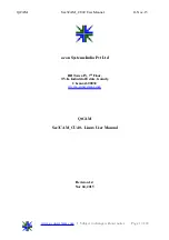
Step 3: Verifying Camera Operation
When power is supplied to the camera while the necessary equipment is connected, the
POWER/TRIG LED at the rear of the camera lights amber, and initialization of the camera
starts. When initialization is complete, the POWER/TRIG LED lights green.
Verify whether power is being supplied to the camera by checking the rear LED.
When properly turned on
Lit green
•
For details on how to read the LEDs, see “LED status and camera status” in the
“Parts Identification” section.
Step 4:
Verifying the Connection between the Camera and PC
Verify whether the camera is properly recognized via Control Tool.
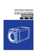
Connecting the Camera to Control Tool
1
Startup eBUS Player for JAI
eBUS Player for JAI startup screen appears.
eBUS Player for
JAI
Device
Control