OM-2245 / Operation and Maintenance Manual
ITW GSE 4400 / 400 Hz. Generator Set
March 15, 2015
Chapter 1-1
Page 13
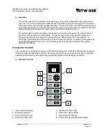
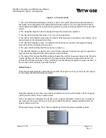
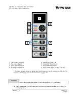
Figure 1-1-5 Control Panel
1: The color LED Graphical Display and easy to use menu system places all required operational
information at the fingertips of the operator/maintenance personnel. Its color presentation accents
critical data and simplifies the troubleshooting process by giving textual descriptions of any potential
issues.
2: The navigation keypad is used to navigate through the simple menu systems.
3: The blue LED indicates that power is on. (It is off in sleep mode)
4: The Amber LED indicates a warning. The details of that warning are available on the display. Up to
five warnings can be displayed at one time.
5: The Red LED indicates a fault. The details of this fault are also visible on the graphics display.
Only one fault can be displayed at one time.
6: The green LED’s indicate that the respective output is on.
7: The ON/OFF buttons are used to turn on and off their respective outputs. If a specific output has a
fault, the corresponding ON/OFF button will also reset that fault.
8: The power ON & Engine Start/Stop button will wake the unit from low-power sleep mode. Pressing
it again will begin the start-up sequence for the diesel engine. Pressing it again will shut down the
engine. If the engine is already running, it will begin the manufacturer required 5 minute cool down. If
the unit has a fault, this button will reset the fault.
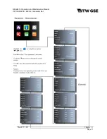
Default Screen:
There are two default displays depending on whether the engine is running or not. When the engine
is not running, the following screen is visible:
During the startup process, the screen will be modified to show the current status until the engine is
running and the unit is ready to output power.
Note: If the engine is configured to go to idle until an output is activated, it will still say it is ready for
use. However, the engine will have to ramp up to 2000 RPM and the voltage stabilized before the
output contactor will close.
When output power is ready, the screen will appear as follows showing all available outputs:
Содержание 4400
Страница 2: ......
Страница 48: ...OM 2245 Operation and Maintenance Manual ITW GSE 4400 400 Hz Generator Set March 15 2015 Chapter 1 3 Page 11 ...
Страница 49: ...OM 2245 Operation and Maintenance Manual ITW GSE 4400 400 Hz Generator Set March 15 2015 Chapter 1 3 Page 12 ...
Страница 50: ...OM 2245 Operation and Maintenance Manual ITW GSE 4400 400 Hz Generator Set March 15 2015 Chapter 1 3 Page 13 ...
Страница 60: ...OM 2245 Operation and Maintenance Manual ITW GSE 4400 400 Hz Generator Set March 15 2015 Chapter 1 3 Page 23 ...
Страница 61: ...OM 2245 Operation and Maintenance Manual ITW GSE 4400 400 Hz Generator Set March 15 2015 Chapter 1 3 Page 24 ...
Страница 112: ...OM 2245 Operation and Maintenance Manual ITW GSE 4400 400 Hz Generator Set This page is intentionally left blank ...
Страница 204: ...OM 2245 Operation and Maintenance Manual ITW GSE 4400 400 Hz Generator Set This page is intentionally left blank ...
Страница 211: ...OM 2245 Operation and Maintenance Manual ITW GSE 4400 400 Hz Generator Set This page is intentionally left blank ...
Страница 212: ......
Страница 213: ......


