OM-2245 / Operation and Maintenance Manual
ITW GSE 4400 / 400 Hz. Generator Set
March 15, 2015
Chapter 3-1
Page 3
The exciter armature is mounted on the main generator armature shaft with a 3/8-inch square machine
key that is held in place by a key retainer, and an M12-1.75 hex head cap screw in the center of the diode
mounting plate.
3) Exciter Armature Replacement
a) General
As stated earlier, exciter armature removal is often required for rear bearing replacement rather than
for replacement of the exciter armature itself. Other reasons for exciter armature removal are
generator armature replacement, general overhaul, etc.
b) Tools needed for Exciter Armature Removal and Installation
In addition to the standard mechanic’s hand tools such as wrenches, etc., you will need only the
following items for removing the exciter armature:
x
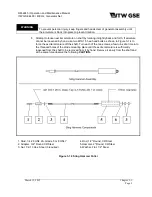
A small, lightweight, sling-hammer puller
x
Two M10-1.5 x 127 mm long fully-threaded hex-head bolts
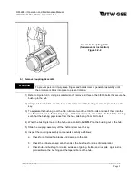
A small, lightweight, sling-hammer puller is shown in Figure 3-1-3. This tool is necessary for
removing the threaded machine key, which keeps the exciter armature from spinning on the
generator armature shaft. You may have such a puller in your equipment inventory. If not, Figure
3-1-3 also illustrates components and dimensions for fabricating such a tool. Sling-hammer pullers
are also commercially available. Instructions for using tool are provided in this manual.
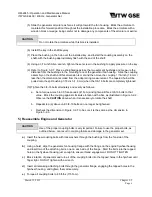
Once the threaded machine key is removed, No other special tools are required for removing the
exciter from the generator shaft. This can be done using the two M10-1.5 fully-threaded hex-head
bolts. Instructions for doing this are provided in this manual.
c) Conditions for Exciter Removal
The mechanics performing the work must decide upon the best and most convenient method of
removing the exciter armature. If the exciter armature is being replaced, then the work may be
performed without removing the generator from the machine. In a great majority of cases, exciter
removal will be for the replacement of the rear bearing. This operation can also be accomplished
without removing the generator. Replacement of the front bearing requires removal of the generator
from the unit.
d) Preparation for Exciter Armature Removal
(1) Remove exciter cover from end canopy and the exciter armature cover from the end of the
generator.
(2) Place a block bar (pry bar) into the generator fan assembly to keep the generator armature from
rotating.
WARNING
To prevent personal injury, keep fingers and hands clear of generator assembly until
the armature is block into place to prevent rotation.
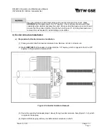
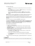
(3) Remove exciter housing cover as required. Remove the M12-1.75 cap screw, which holds the
exciter armature and key retainer on the generator shaft.
Содержание 4400
Страница 2: ......
Страница 48: ...OM 2245 Operation and Maintenance Manual ITW GSE 4400 400 Hz Generator Set March 15 2015 Chapter 1 3 Page 11 ...
Страница 49: ...OM 2245 Operation and Maintenance Manual ITW GSE 4400 400 Hz Generator Set March 15 2015 Chapter 1 3 Page 12 ...
Страница 50: ...OM 2245 Operation and Maintenance Manual ITW GSE 4400 400 Hz Generator Set March 15 2015 Chapter 1 3 Page 13 ...
Страница 60: ...OM 2245 Operation and Maintenance Manual ITW GSE 4400 400 Hz Generator Set March 15 2015 Chapter 1 3 Page 23 ...
Страница 61: ...OM 2245 Operation and Maintenance Manual ITW GSE 4400 400 Hz Generator Set March 15 2015 Chapter 1 3 Page 24 ...
Страница 112: ...OM 2245 Operation and Maintenance Manual ITW GSE 4400 400 Hz Generator Set This page is intentionally left blank ...
Страница 204: ...OM 2245 Operation and Maintenance Manual ITW GSE 4400 400 Hz Generator Set This page is intentionally left blank ...
Страница 211: ...OM 2245 Operation and Maintenance Manual ITW GSE 4400 400 Hz Generator Set This page is intentionally left blank ...
Страница 212: ......
Страница 213: ......

