OM-2245 / Operation and Maintenance Manual
ITW GSE 4400 / 400 Hz. Generator Set
March 15, 2015
Chapter 1-1
Page 11
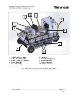
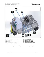
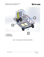
(2) Radiator and Charge-Air-Cooler (CAC)
The radiator and charge-air-cooler is a two-piece type designed for long periods of operation
without servicing.
(3) Engine-cooling fan
The engine fan is designed to blow air outward through the radiator, rather than pulling the air
inward as a conventional fan does.
(4) Master [Battery] Disconnect Switch
The master disconnect switch is designed to isolate the batteries from the entire electrical system
to eliminate the possibility of battery current draw by the engine ECM or any other components
during long periods of no operation. The switch can also be used to lock-out the starting circuit of
the equipment for maintenance safety purposes.
(5) Air cleaner
The diesel engine air cleaner is so constructed that air enters through its cylindrical body, and
then is filtered before being passed into the engine turbo-charger assembly. An air cleaner
service indicator device is mounted on the air cleaner assembly to monitor the airflow into the air
cleaner. As the air cleaner becomes filled with dust, dirt, and carbon, the intake system airflow
becomes increasingly restricted. This restriction causes a diaphragm inside the indicator to move
toward an electrical contact. When the maximum allowable restriction level is reached, the circuit
closes and the air cleaner indicator fault appears on the control panel fault display to warn the
operator that the air cleaner must be changed. The electrical indicator automatically resets when
the restriction level drops sufficiently. Note: This function should not be used as a replacement
indicator. Follow recommended replacement schedule as specified in this manual.
d) Warnings/Faults
The control system reacts appropriately to different detected issues. These types can be generalized
between warnings and faults. Warnings are given when the system is able to function but requires
servicing/user interaction. Faults are generated when the unit cannot or should not supply regulated
power to the aircraft.
All faults prevent the engine from starting. However, they react differently to an operating unit. Faults
can be categorized into three subcategories as defined by the fault number.
x
Fault numbers less than 6000
o
Minor faults: Disconnect power to the aircraft but do not affect engine and generator
functions.
x
Fault numbers between 6000 and 8000
o
Mid-level faults: Disconnect power to the aircraft, turn off the generator and shut down
the engine after the required 5 minute cool down.
x
Fault numbers greater than 8000
o
Major faults: Result in immediate shutdown of all system components including the
engine. Service is required on the unit before it is returned to operation.
Engine generated warnings and faults are also monitored and their respective Cummins fault
numbers are shown on the display.
Содержание 4400
Страница 2: ......
Страница 48: ...OM 2245 Operation and Maintenance Manual ITW GSE 4400 400 Hz Generator Set March 15 2015 Chapter 1 3 Page 11 ...
Страница 49: ...OM 2245 Operation and Maintenance Manual ITW GSE 4400 400 Hz Generator Set March 15 2015 Chapter 1 3 Page 12 ...
Страница 50: ...OM 2245 Operation and Maintenance Manual ITW GSE 4400 400 Hz Generator Set March 15 2015 Chapter 1 3 Page 13 ...
Страница 60: ...OM 2245 Operation and Maintenance Manual ITW GSE 4400 400 Hz Generator Set March 15 2015 Chapter 1 3 Page 23 ...
Страница 61: ...OM 2245 Operation and Maintenance Manual ITW GSE 4400 400 Hz Generator Set March 15 2015 Chapter 1 3 Page 24 ...
Страница 112: ...OM 2245 Operation and Maintenance Manual ITW GSE 4400 400 Hz Generator Set This page is intentionally left blank ...
Страница 204: ...OM 2245 Operation and Maintenance Manual ITW GSE 4400 400 Hz Generator Set This page is intentionally left blank ...
Страница 211: ...OM 2245 Operation and Maintenance Manual ITW GSE 4400 400 Hz Generator Set This page is intentionally left blank ...
Страница 212: ......
Страница 213: ......


