OM-2245 / Operation and Maintenance Manual
ITW GSE 4400 / 400 Hz. Generator Set
March 15, 2015
Chapter 2-4
Page 13
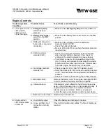
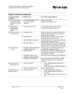
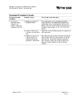
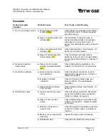
Protective Circuit
NOTE:
Protective monitoring is not completely functional until the load contactor is CLOSED. Since it is not
advisable to vary voltages for test purposes while delivering power to an aircraft, the GPU should be
connected to a load bank for trouble shooting protective circuits.
Trouble, Symptom,
Condition
Probable Cause
Test, Check, and/or Remedy
1.
Load contactor
opens during power
delivery. Over
voltage fault
indicated.
a.
Over-voltage condition
may have been the result
of a sudden drop in load
and may have been a
normal action.
Press appropriate
Output
pushbutton and resume
power delivery. Observe voltmeter to be certain
voltage is normal (115 VAC). Adjust to normal if
necessary. If load contactor is opened again and
the fault message indicates an over-voltage
condition, proceed to step
b
.
b.
Defective Interface or
control board.
With load bank at no load, use the Output Voltage
screen in the Setup menu (Chapter 1-3 Paragraph
4.1) to reduce the voltage to 110 VAC. Observe
the voltmeter on the load bank and gradually
increase voltage. If the load contactor opens at any
value less than 125 VAC replace the interface and
processor board.
2.
Load contactor
opens during power
delivery. Under
voltage fault
indicated.
a.
Under-voltage condition
may have been result of
a sudden shock load, or
possible tampering with
REG potentiometer, and
may have been a normal
action.
Press appropriate
Output
pushbutton and resume
power delivery. Observe voltmeter to be certain
voltage is normal (115 VAC). Adjust to normal if
necessary. If load contactor is opened again and
the fault message indicates an under-voltage
condition, proceed to step
b
.
b.
Defective Interface or
Control board.
With load bank at no load, use the Output Voltage
screen in the Setup menu (Chapter 1-3 Paragraph
4.1) to slowly reduce the voltage to 100 VAC. If the
load contactor opens at any value above 104 VAC,
replace the interface and processor board.
Содержание 4400
Страница 2: ......
Страница 48: ...OM 2245 Operation and Maintenance Manual ITW GSE 4400 400 Hz Generator Set March 15 2015 Chapter 1 3 Page 11 ...
Страница 49: ...OM 2245 Operation and Maintenance Manual ITW GSE 4400 400 Hz Generator Set March 15 2015 Chapter 1 3 Page 12 ...
Страница 50: ...OM 2245 Operation and Maintenance Manual ITW GSE 4400 400 Hz Generator Set March 15 2015 Chapter 1 3 Page 13 ...
Страница 60: ...OM 2245 Operation and Maintenance Manual ITW GSE 4400 400 Hz Generator Set March 15 2015 Chapter 1 3 Page 23 ...
Страница 61: ...OM 2245 Operation and Maintenance Manual ITW GSE 4400 400 Hz Generator Set March 15 2015 Chapter 1 3 Page 24 ...
Страница 112: ...OM 2245 Operation and Maintenance Manual ITW GSE 4400 400 Hz Generator Set This page is intentionally left blank ...
Страница 204: ...OM 2245 Operation and Maintenance Manual ITW GSE 4400 400 Hz Generator Set This page is intentionally left blank ...
Страница 211: ...OM 2245 Operation and Maintenance Manual ITW GSE 4400 400 Hz Generator Set This page is intentionally left blank ...
Страница 212: ......
Страница 213: ......

