background image

81

WARNING:
• As soon as the PTO switch is turned to the

ON (

M

) position, the mower blades start rotat-

ing and eject cut grass or stones through the
discharge opening. Consequently, before
operating the PTO switch make sure that
there is no people, animals, or physical prop-
erties like buildings, cars, etc. within a range
where ejected grass or stones may reach.

• The mower blades should be turned only on

turf or grassland with the mower deck low-
ered.

h. Shift the throttle lever to the high speed position (

r

) to

raise engine speed.

i. As the drive control levers are pushed gradually, the

Zero turn mower starts to travel.

CAUTION:Be sure to start mowing at suffi-
ciently low speeds and increase travelling
speed gradually.

IMPORTANT: The engine hood and the radiator screen

should be kept clean. Never keep on
operating with clogged screens, or the
engine may be overheated, which may
result in engine seizure.

4. EMERGENCY STOP

When any of the following abnormalities is encoun-
tered, stop the zero turn mower and mower deck
immediately.

-  Abnormal noise
-  Abnormal vibration
-  Abnormal smell
-  Blade hitting an obstacle
-  The zero turn mower hitting an obstacle

The cause of trouble should be located and corrected
immediately. If not, consult your dealers. 
Never attempt to keep on operating the zero turn
mower without locating and correcting the cause of
trouble.

When leaving the zero turn mower to remove obsta-
cles such as twigs, pebbles, etc., the PTO switch must
be turned to the OFF (

N

) position and the parking

brake applied.

5. STOPPING MOWING OPERATION

a. Release the dive control levers and shift to lock position.

b. Shift the throttle lever to the low speed position 

(

t

) to reduce engine speeds.

c. Apply the parking brake.

CAUTION:
Park the zero turn mower on level, hard
ground and make sure that the parking
brakes are applied securely.

d. Turn the PTO switch to the STOP (

N

) position.

e. Turn the key switch to the STOP (

$

) position to stop

the engine.

IMPORTANTt:

Never attempt to stop the engine abruptly when it is
running at high speeds.

Be sure to let the engine idle for about 5 minutes after
long operation and then stop the engine. Abrupt
engine stopping may lead to overheating causing
seizure.

f. Remove the starter key and cap the key hole without

fail.

CAUTION:
When you leave the zero turn mower, be sure
to stop the engine and remove the starter key
to prevent the zero turn mower from being
started unexpectedly by children or unautho-
rized people.

IMPORTANT:Be sure to cap the key hole after having

removed the starter key. Otherwise, water
or dust may enter into the switch, which
may cause trouble.

CHAPTER 4. MOWER OPERATION

Содержание SZ330

Страница 1: ...I S E K I Z E R O T U R N M O W E R ZERO TURN MOWER MOWER DECKS SZ330 SSM60 SSM72 ...

Страница 2: ...e delivery service on your new machine He will discuss with you the operating and maintenance instructions gives in this manual and instruct you in the proper and varied applications of this machine Call on him at any time when you have a question or need equipment related do the use of your machine Paragraphs in the manual and labels on the machine which are accompanied by a caution particularly ...

Страница 3: ...T LEVER 31 1 7 FUEL GAUGE 31 1 8 CUTTING HEIGHT ADJUST DIAL 31 2 1 BRAKE PEDAL 32 2 2 PARKING BRAKE LEVER 32 2 3 DRIVE CONTROL LEVER 32 3 OTHER CONTROLS 33 3 1 SAFTY SWITCHES 33 6 PRE OPERATIONAL ROUTINE INSPECTION 34 1 INSPECTION ITEMS 34 2 WAY OF INSPECTION AND MAINTENANCE 34 7 OPERATION 35 1 BEFORE STARTING THE ENGINE 35 2 STARTING THE ENGINE 36 3 STOPPING THE ENGINE 37 4 TRAVELLING 38 5 STOPPI...

Страница 4: ...70 1 BEFORE OPERATION 70 2 CUTTING HEIGHT ADJUSTMENT 70 3 STARTING MOWING OPERATION 71 4 EMERGENCY STOP 72 5 STOPPING MOWING OPERATION 72 6 EFFICIENT MOWING 73 5 INSPECTION AND MAINTENANCE OF MAJOR PARTS 74 1 INSPECTION AND REPLACEMENT OF GEAR CASE OIL 74 2 INSPECTION AND REPLACEMENT OF TIMING BELT 75 HOW TO JACK UP 76 3 INSPECTION REPLACEMENT OF BLADES 78 Blade Removal 78 Shimming of Blades 78 4 ...

Страница 5: ... SSM Definitions Power Take Off Permanent Type Right hand and Left hand sides are determined by facing in the direction of forward travel Roll Over Protective Structure Revolutions Per Minute Society of Automotive Engineers Side discharge Mower ZERO TURN MOWER ...

Страница 6: ...e Stop Engine Run Starter Control Engine Revolution Fast Slow Mower deck Mower Lowered position Mower Raised position Cutting Height Power Take Off Clutch Control Off position Power Take Off Clutch Control On position Battery Diesel Fuel P Parking Brake UNIVERSAL SYMBOLS ...

Страница 7: ...rate adjust and servise the Zero turn mower properly Before starting to operate the Zero turn mower for the first time you should read this operation manual thoroughly and carefully until you are sufficiently familiar with the operation of the Zero turn mower in order to do jobs safely and properly You are advised to refer to it from time to time to refresh your understanding of the Zero turn mowe...

Страница 8: ...om serious injury Do not operate the Zero turn mower while you are under the influence of alcohol or drugs 1 5 Understand how to properly and safely operate and maintain the Zero turn mower Seek and obtain practical instruction on how to operate and maintain the Zero turn mower properly 1 6 Be sure to use necessary protective devices such as headgear safety glasses safety shoes ear plugs gloves et...

Страница 9: ...lly If not this may not only shorten the Zero turn mower s service life but also make safe and efficient operation impossible 1 10 Never use the front mower out of normal usage even if it is not mentioned at this operation manual ZERO TURN MOWER ...

Страница 10: ...operly 2 6 Start the engine from the operating or designated starting position 2 7 Before starting the engine make sure that every thing is safe around the Zero turn and put the trac tion drive in neutral set parking brake and disen gage the cutting unit s Otherwise unexpected accidents may occur 2 8 Start the engine with the starter switch only Never attempt to start the engine by shorting the te...

Страница 11: ...ng nuts are not worn dam aged or loose Replace worn or damaged blade and nuts as an assembly to preserve blade balance Otherwise poor braking or scattered broken blades may result which is very dangerous 2 17 When operating the Zero turn mower equipped with attachment which is not ISEKI made at the slope be sure to equip with Zero turn mower with balance weights Order the following parts to secure...

Страница 12: ...Do not attempt to adjust the cutting height while the engine is running 3 16 Adjust the cutting height with the gauge wheels in accordance with the condition of the ground surface at the working site Mowing on rough ground with low cutting height may cause the blades to hit soil or stones which is very dangerous 3 17 If you strike an object or if the Zero turn mower vibrates abnormally stop the fr...

Страница 13: ...ch to the OFF position 3 29 Before leaving the operating position of the Zero turn for any reason always do the following Stop the Zero turn on level ground Stop the cutting unit s disengage PTO and lower the attachment s Disengage the drive s Set the parking brake Stop the engine and wait for all moving parts to stop ZERO TURN MOWER ...

Страница 14: ...mower is not equipped with any attach ments or a cabin The Zero turn mower is equipped with a standard mower deck Grass catchers and other attachments can change the stability of the Zero turn mower Follow the instructions for adding weight to improve the stability of the Zero turn mower When your Zero turn mower is equipped with an imple ment other than standard such as a collector a cabin etc ne...

Страница 15: ... down a slope Engage the clutch slowly and always keep the Zero turn mower in gear especially when travelling downhill 4 11 Do not use the grass catcher s while you are mow ing a steep slope 4 12 Do not try to stabilize the Zero turn mower by put ting your foot on the ground 4 13 Avoid stopping the Zero turn mower on a slope 5 DRIVING ON PUBLIC ROADS 5 1 This Zero turn mower cannot be driven on a ...

Страница 16: ... for loading and unloading the mower Avoid switching from forward motion to backward motion or vice versa as this will cause the front wheels to rotate sideways Sideway rota tion of the front wheels poses some danger when the mower is on the ramp 6 4 When loading the Zero turn mower onto a truck lift up the mower deck fully and rearward it straight at sufficiently low speeds Drive it advance when ...

Страница 17: ...e platform for it changes angles abruptly 6 9 When the Zero turn mower is loaded on the truck lower the mower deck onto the truck bed stop the engine apply parking brakes and withdraw the starter key chock the wheels and rope it securely to the truck Refrain from unnecessary abrupt start ing stopping and turning during transportation or the Zero turn mower may shift position on the truck which is ...

Страница 18: ...G AND DISMOUNTING OF THE MOWER DRIVE SHAFT The mower gear box is driven through a drive shaft with universal joints from the Zero turn mower When connect ing or disconnecting the shaft follow the next instructions 8 1 Lower the mower deck onto the gournd stop the engine draw the engine key and apply the parking brakes before mounting or dismounting the drive shaft 8 2 Shift the PTO switch to the O...

Страница 19: ...gine Careless removal of the radiator cap can cause serious injury because of superheated water vapor 9 9 Before servicing the Zero turn mower be sure to turn off the PTO switch to the OFF position and make sure that the mower blades have stopped completely Rotating blades may casue serious accidents 9 10 While adjusting the Zero turn mower keep your fin gers away from all pinch points 9 11 When s...

Страница 20: ... to be drained this should be done out doors 9 22 Check the brake s on the front mower frequently and adjust and service the brake s as required 9 23 Replace faulty mufflers silencers 9 24 Do not change the engine governor settings or overspeed the engine Operating an engine at an excessive speed can increase the risk of personal injury 9 25 The grass catcher components are subject to wear and dam...

Страница 21: ...20 9 29 Check that all safety devices are in place and oper ating properly ZERO TURN MOWER ...

Страница 22: ...also cause short circuit or leakage of electricity which may lead to a fire Promptly repair or replace damaged wiring 4 Remove chaff or dust from the battery wiring muf fler or engine Otherwise it could result a fire 10 2 TO HANDLE THE BATTERY 1 When working around the battery avoid smoking The battery generates explosive hydrogen and oxy gen gases when it is being charged Keep the bat tery away f...

Страница 23: ... This will lower the force in case of explosion 2 Before connecting cables be sure to stop the engines Otherwise unexpected accidents may occur 3 Use booster cables with sufficient electrical capacity A cable of inadequate capacity will cause generation of heat which may lead to a fire 11 TYRES AND WHEELS 11 1 Be sure to keep tyre pressures at the levels speci fied in this manual Excessively high ...

Страница 24: ... ventilation for exhaust gases Exhaust fumes can be lethal 12 7 To avoid fire hazard keep the engine muffler bat tery and fuel storage area free of grass leaves or excessive grease 12 8 Never cover a hot Zero turn mower just after opera tion with a tarpaulin or the like or the heated engine and related parts may cause a fire 13 LONG TERM STORAGE 13 1 Never store the mower with fuel in the tank ins...

Страница 25: ...the machine apply the parking brakes shut off the engine and remove the engine key e Risk of injury Keep all safety devices such as guards safety switches etc in place and working properly f Risk of injury Remove objects from around the machine that could be thrown by blades and keep people away from the machine before starting the machine g Risk of running over a person Watch behind before revers...

Страница 26: ...arks or flames When charging or using provide suffi cient ventilation Watch out when using booster cables Battery electrolyte sulphuric acid may cause blind ness or burns Avoid allowing electrolyte to contact eyes skin or clothing In the event of an accident flush area immediately with plenty of water If acid gets into the eyes rinse with plenty of water any get medical attention 3 2 Caution label...

Страница 27: ... 4 Belt caution label Stay clear of the belt while it is running 5 Fan caution label Stay clear of the fan while it is running 26 5 4 3 5 FIG 18 FIG 19 ZERO TURN MOWER ...

Страница 28: ... system Do not open cap while radia tor is hot 7 Starter caution label Start engine only with key from seat 8 Hot parts caution label Stay clear of the heated parts while they are hot 6 7 4 3 5 8 FIG 20 FIG 21 FIG 22 CHAPTER 1 FOR SAFE OPERATION ...

Страница 29: ...njury Read operator s manual before raising machine Park on film level ground Engage parking brake Shut off engine and remove key Block up mower with additional support Lock lift mechanism in place before raising machine and making adjustments underneath Store lift mechanism when complete U complete machine and making adjustments underneath Store lift mechanism when place before raising Lock lift ...

Страница 30: ...ome dirty wash them with soapy water and wipe off with soft cloth If any of them are torn or lost order new labels from your dealer A new label should be placed in the same place where the old one was located When sticking on a new label clean the place to enable the label to stick and squeeze out all air bub bles trapped under it When replacing a part with a caution label stuck on a new caution l...

Страница 31: ...n mower and mower deck refer to the warranty policy attached AFTER SALE CARE As for manual dunp question about the Zero turn mower and mower deck consult with your dealers identifying the model and serial number of your Zero turn mower CHAPTER 2 WARRANTY AND AFTER SALE CARE 1 2 FIG 26 FIG 27 Type RE42C RE42F2 For France SSM60 SSM72 Type 1524mm 60 1830mm 72 For France ZERO TURN MOWER ...

Страница 32: ... transmission Rear axle Traveling speeds Foward engine max rpm km h mph Reverse km h mph mm in Front mm in Rear std mm in mm in without mower deck mm in with mower deck mm in Front Rear Location Type Drive On Off Revolution rpm Mower deck lifting Height adjusting Pump capacity cc rev Max output liter min degrees 31 CHAPTER 3 SPECIFICATIONS Model SZ330 2320 91 3 1480 58 3 2280 89 8 1290 50 8 1950 7...

Страница 33: ...opt std std std std opt opt std 32 ACCESSORIES Front weight hitch Fuel gauge Water temp warning buzzer Hour meter Jack Seat Seat belt ROPS Model SZ330 ZERO TURN MOWER ...

Страница 34: ... 2 Fuel tank cap 3 Seat belt 4 Drive control lever 5 Front cover 6 Parking brake lever 7 Brake pedal CHAPTER 4 NAME OF MAJOR COMPONENTS 5 4 4 1 2 3 6 7 STOP QUARTZ HOURS FIG 28 CHAPTER 4 NAME OF MAJOR COMPONENTS ...

Страница 35: ... 1 Starter switch 2 Throttle lever 3 Monitor lamp array 4 PTO switch 5 Hour meter 6 Mower deck lift lever 7 Fuel gauge 8 Cutting height adjust dial CHAPTER 5 CONTROLS AND METERS 2 1 4 8 7 3 5 6 25 FIG 29 ZERO TURN MOWER ...

Страница 36: ...ion while the engine stops but turns off as soon as the engine starts Oil pressure lamp o The lamp lights up when the engine oil pressure is not circulating normally It also lights up when the key turns to the ON O position or the START c position while the engine stops but turns off as soon as the engine starts Engine coolant warning lamp W The lamp lights up when the engine coolant is over heate...

Страница 37: ...ition indicated by this mark and the PTO shaft stops spinning Turn the switch counter clockwise to disengage 1 5 HOURMETER The hourmeter counts operation hours of the Zero turn mower and shows them The lower figure indicates a tenth of an hour of operation 1 6 LIFT LEVER With this lever the lift link is raised or lowered d in this position the lift link is lowered u in this position the lift link ...

Страница 38: ...he Zero turn mower be sure to apply the parking brake 2 3 DRIVE CONTROL LEVER Manipulate these control levers to move the Zero turn mower forward or backward To move forward push both control levers To move backwards pull both control levers Adjust the forward backward speed by adjusting the amount of push pull on these levers To increase speed increase the amount of pull or push on the levers To ...

Страница 39: ...switch Engine hood open switch only F2 type Please perform the following steps before starting the engine 1 Engine hood is Closeed and The operater should be seated in the operater s seat 2 Make sure that both left and right control levers are in the locked position 3 Step on the brake pedal to its maximum 4 Make sure that the PTO switch is switched OFF IMPORTANT The operator seat has a safety swi...

Страница 40: ...ch which sounds off an alarm to the driver to prevent forward backward move ment of the mower while the brakes are engaged CAUTION If the safety switches do not work properly please consult the dealer nearest to you CHAPTER 5 CONTROLS AND METERS ...

Страница 41: ...flation Exterior parts broken or deformed covers or the like Oil leakage engine oil transmisshion oil fuel etc Inspection and cleaning of air intake port Inspection of engine oil level Inspection of coolant level Inspection of fan belt Inspection of fuel level Inspection of fuel filter Inspection of transmission oil level Inspection of front and rear wheel tightening bolts and nuts Cleaning of rad...

Страница 42: ...entilation for exhaust fumes can be lethal IMPORTANT Perform the following operations before starting the engine a Close the engine hood properly b Sit in the operators seat properly c Set the drive control lever 1 to the locked position d Step on the brake pedal 2 to its maximum e Turn off the PTO switch 3 f Insert the starter key into the starter switch and turn the key to the ON position O Make...

Страница 43: ...he starter key The key will return automatically to the ON position O j Make sure that the charge lamp and oil pressure lamp turn off IMPORTANT If the oil pressure should remain lit stop the engine immediately and check the engine lubrication system k When the engine starts shift the throttle lever 1 to an intermediate speed position that is between the high speed and low speed positions r and t L...

Страница 44: ...ut 5 minutes after a longtime operation and then stop the engine Abrupt engine stopping may lend to overheating caus ing seizure d Remove the starter key and cap 3 the key hole with out fail CAUTION When you leave the Zero turn mower be sure to stop the engine and remove the starter key to prevent the Zero turn mower from being started unexpectedly by children or unauthorised people IMPORTANT Be s...

Страница 45: ...er blades to hit stones or stocks which may result in break down of the Zero turn mower or serious accidents c Release the parking brake lever d Shift the throttle lever to the high speed position r to accelerate the engine IMPORTANT For your safety before moving forward the Zero turn mower check the conditions in front of and around the Zero turn mower WARNING Never attempt to turn the Drive cont...

Страница 46: ...d Shift the lift lever to down position d to lower the mower deck onto the ground CAUTION When stopping the Zero turn mower lower the mower deck onto the ground without fail to avoid accidents unexpectedly 6 PTO SWITCH PTO switch 1 is used to engage and disengage the PTO drive system The switch must first be turned to right and then pulled up to engage PTO To disengage PTO push the PTO control swi...

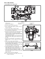
Страница 47: ...ro turn mower after the engine has cooled down sufficiently With these items in mind confirm the safety conditions for maintenance operation with out fail ahead of time Servise access Opening Closing hood To release the hood move the open close level1 in the direction shown by the arrow Open the hood by grasping and lifting up the front of the food Folding seat and suspension forward To fold seat ...

Страница 48: ...o hot just after operation as to cause burns and it takes some time as well for all the oil to return to the oil pan IMPORTANT Never replenish with a different kind of oil The addi tion of different kind of oil will deteriorate the quality of the original oil The oil level should not exceed the upper linmit Excessive oil will cause engine trouble Use oil of the quality recommended by ISEKI or 10W ...

Страница 49: ...s common with oil for the hydrostatic transmission HST and the hydraulic lift cylinder so pay sufficient attention not to allow dust water and other foreign matter to be trapped in the oil 3 COOLANT LEVEL WARNING Never remove the radiator cap during or just after operation The water in the radiator is very hot and highly pressur ized so it may cause burns Allow the engine to cool down sufficiently...

Страница 50: ...de by the following items or a fire may be caused Before replenishing with fuel be sure to stop the engine and wait until the engine and heated parts cool down sufficiently Keep sparks open flames etc away from th fuel tank No smoking Spilt fuel should be wiped away immedi ately IMPORTANT As soon as the fuel gauge shows E replenish with fuel Never attempt to keep on operating with oil level lower ...

Страница 51: ...sed air from inside to outside of the ele ment f When the element does not become sufficiently clean only by blowing dip it in neutral detergent solution for about 30 minutes and then rinse it in fresh water Then dry it in the atmospheric temperature g After cleaning install the element in reverse order of disassembly IMPORTANT Never hit the element against a hard object like a con crete wall An e...

Страница 52: ...ill the fuel tank 2 Turn the fuel cook to Open position 3 Loosen the air bleeding screw and let air bubbles out 7 INSPECTION OF FUEL HOSES Check the fuel hoses for cracks and fuel leak after every 100 hours of operation A damaged hose should be replaced with a new one 8 FAN BELT WARNING Before checking the fan belt stop the engine and remove the starter key without fail Wait until the engine and a...

Страница 53: ... right of the step to its limit Then adjust the adjust bolt so that the notch of the parking lever 2 locks at the third level b Adjust the brake rod 4 with the parking brake so that the space between the coils of the pair of brake springs 5 is set to 0 9 mm 0 35 in c Start the engine and drive the zero turn mower for ward at a low speed Step on the brakes and check if the brakes are working evenly...

Страница 54: ...their maximum a Remove the boots of the drive control lever at the side to which the mower tends to curve b Slightly tighten the adjust bolt 1 at the side to which the mower tends to curve by tightening the lock nut c Start the engine and drive forward to check how much the zero turn mower curves d The curvature should be no more than 3 meters after traveling for 20 meters e When the curvature is ...

Страница 55: ... the adjust plate c Adjust the control levers so that their clearance is about 35 mm 1 38 in Tighten the adjust bolts d Re install the boots to their original position DANGER Please make sure that the engine is turned off before adjusting the adjust bolts Insufficient clearance in both left and right control levers can lead to abnormal operation of the zero turn mower Therefore the clear ance limi...

Страница 56: ...pt clean and connectors tight Dirty or loose wiring may cause a fire When disconnecting the battery disconnect the negative terminal first and vice versa when connecting When replacing the battery use a battery of the same capacity as that of the current on 55B 24 R a As atmospheric temperature lowers the performance of the battery also lowers Consequently the battery should be serviced with speci...

Страница 57: ...rten tire life time 17 ENGINE OIL REPLACEMENT IMPORTANT The engine oil should be replaced with fresh oil in accordance with operation hours If not overly used oil will cause engine troubles The first replacement should be done after the initial 50 hours of operation and then after every 100 hours of operation When replacing engine oil place the Zero turn mower on level hard ground The engine oil d...

Страница 58: ... 50 hours of operation and then after every 300 hours of operation It is recommended to ask your dealer to replace the engine oil filter because this operation requires a spe cial tool But when there is no alternative but to replace the filter by yourself observe following instruc tions a Drain engine oil completely following the instructions of 17 ENGINE OIL REPLACEMENT b Place some rags under th...

Страница 59: ...ont of the HST pump case under the seat a Remove the bolts of the seat base and then turn the seat b After the HST oil has drained out from the drain plugs 1 2 completely remove the filter using the filter spanner When removing the filter a small amount of oil may spill so place waste cloth under the filter to receive spilt oil c Apply thin coat of oil to the O ring of the new oil filter cartridge...

Страница 60: ...ator screen IMPORTANT Avoid using excessively compressed air or water which may deform the cooling fan blades Avoid applying water directly to the wiring and electric apparatus After washing the radiator using water from a tap let it dry by itself 23 COOLANT REPLACEMENT WARNING Never attempt to remove the radi ator cap during or just after operation or pressurized vapor and hot water will gush out...

Страница 61: ...If the level is low replenish the reserve tank with coolant IMPORTANT Never attempt to run the engine without coolant or the engine will seize leading to its complete damage 24 INSPECTION OF FUSES AND WIRING The fuse box is located in the right hand side inside the engine room of the Zero turn mower CAUTION The 20A fuse in fuse box is not a spars fuse It is installed to provide power to the electr...

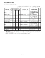
Страница 62: ... seated in the operator s seat b Turn the PTO switch to the ON M position c Set the drive control lever to the neutral open lock position d Depress the brake pedal e Turn the key switch to the START c position f Make sure that the engine is not cranked INSPECTION 2 a Be seated in the operator s seat b Shift the PTO lever to the OFF N position c Set the drive control lever to the drive position d D...

Страница 63: ...link Braek pedal hub Front axle center pivot Drive counter link Front tire yoke LH Front tire yoke RH Mower lift link Front tire hub LH Front tire hub RH Fresh clean water and LLC 50 Hydraulic oil ISO VG46 Gear oil SAE80 Gear oil SAE80 Diesel fuel Engine oil Grease Grease Grease Grease Grease Grease Grease Grease Grease Grease Grease 4 8 1 06 1 1 0 24 10 2 2 0 5 0 11 0 5 0 11 36 7 92 4 5 0 99 As r...

Страница 64: ...hr Replace after every 300hr Replace after initial 50hr Replace after every 300hr Replace after initial 50hr Replace after every 200hr Replace after initial 50hr Replace after every 200hr Inject grease after every 50hr Check after every 200hr Judgement criteria Maintain the specified level Maintain the specified level Keep fuel tank always full There should be no dust or water in filter 10mm 0 4 i...

Страница 65: ...ank and close the fuel cock c Replace the engine oil with new and let the engine idel for about 5 minutes to lubricate every part sufficiently d Lubricate all lubrication points e Grease up all greasing points f Check bolts and nuts for looseness and re tighten loose ones g Inflate each tyre a little higher than specified h Dismount the mower deck or lower it to the ground CAUTION A lifted up mowe...

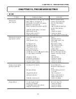
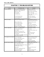
Страница 66: ...jection nozzles Air trapped in fuel system Improper earthing Clogged fuel strainer Leaking fuel system Defective injection pump Too low engine oil level Engine is overheated Coolant temperature does not rise Defective injection pump Remedies Shift it to neutral position Depresse the brake pedal Turn it to OFF position Charge it Clean the terminal posts and connect them securely Rewire Consult your...

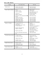
Страница 67: ...y Clogged engine oil filter Defective oil pump Defective oil pressure switch Clogged air cleaner Too high engine oil level Insufficient fuel injection Defective Clogged intake system Remedies Consult your dealers Consult your dealers Supply with fuel Clean element Raise cutting height or slow down Zero turn mower Use proper diesel fuel Cool down engine Shift it there securely Consult your dealers ...

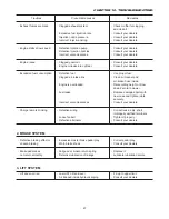
Страница 68: ...gged air intake line Engine is overloaded Fuel leaks Incorrect valve clearances Use proper fuel Clean air cleaner and air intake hose inside Raise cutting height or slow down Zero turn mower Replace damaged parts with new ones and tighten joints securely Consult your dealers Charge lamp is blinking Defective wiring Loose fan belt Defective alternator Correct loose dirty short improperly earthed te...

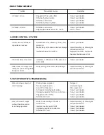
Страница 69: ... translatory movement Imbalance in efficiencies of the pump and motor pairs Consult your dealer Differences in the alignment of the lever pairs during trans latory movement Faulty setting of the control lever linkage Adjust the setting by following the manual instructions Zero turn mower does not start travelling Parking brake is applied Too low engine speed Low HST oil tank level Air trapped insi...

Страница 70: ...th and short circuit Repair defective parts Tighten belt as specified Correct loose terminals and corroded parts Otherwise install a new battery Consult your dealers Moniotor lamps do not light up Defective contact Re connect connector Fuel pump does not work Blown fuse Defective fuel pump Check the wiring and replace the blown fuse with a new one Consult your dealers Fuel cut off solenoid does no...

Страница 71: ...ZERO TURN MOWER 70 ...

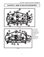
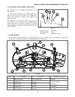
Страница 72: ...ver LH 5 Belt cover RH 6 Discharge cover 7 Gear case 8 Pulley 9 Belt 10 Tension spring 11 Tension arm 12 Tension pulley 13 Mid roller CHAPTER 1 NAME OF MAJOR COMPONENTS 1 2 3 3 4 5 13 3 3 6 8 7 9 8 12 11 10 FIG 81 FIG 82 CHAPTER 1 NAME OF MAJOR COMPONENTS ...

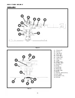
Страница 73: ... 6 Output shaft 7 Gear case 8 Pulley 9 Metal center 10 Grease nipple 11 Nut M16 12 Pulley 13 Shaft side 14 Metal side 15 Collar brade 16 Brade 17 Washer 20 60 06 18 S W M20 19 Nut M20 1 5 20 Washer 1 2 3 4 5 6 7 8 9 10 11 10 12 13 14 15 16 17 19 18 20 FIG 83 FIG 84 ZERO TURN MOWER ...

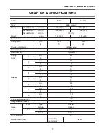
Страница 74: ...ensions Overrall length Overrall width Overrall height mm in mm in mm in kg lb mm in Weight No of blades Direction of discharge Mower deck drive Mower deck lift Cutting height 8 stages Cutting height adjustment Gauge wheel adjustment No of limit roller Material of limit roller Front rubber Rear plastic Plastic Gauge wheel Front Type Material Type Material Rear 1 2 3 4 5 6 7 8 mm in mm in mm in mm ...

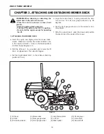
Страница 75: ...position u to raise the lift link 2 to highest level Then stop the engine c Set the height adjust dial 7 to the minimum trimming position 25 mm 1 Lift lever 4 Mower deck 7 Height adjust dial 10 Parking lever 2 Lift link 5 Rear gauge wheel 8 Link pin 11 Drive shaft 3 Front wheel caster 6 Front gauge wheel 9 Brake pedal 12 Adjust shaft d Align the mower deck 4 to along side with the Zero turn mower ...

Страница 76: ...ial to the minimum trimming position 25 mm When attaching detaching the mower deck to and from the Zero turn mower unit please make sure that the upper end of the adjust shaft 12 of the rear gauge wheels does contact the transmission unit of the Zero turn mower When installing the drive shaft 11 check if the retain ing lock is set properly or not 2 DETACHING THE MOWER DECK Detach the mower deck in...

Страница 77: ...the low est height f Adjust the rear edge height of the right blade by nut 4 on right side so that the height fits the front edge height g Measure the rear edge height of left blade If the rear edge height of the left blade is higher than front edge height adjust the height of rear edge by nut 4 so that a play of the rod 5 is lost If the rear edge height of the left blade is lower than front edge ...

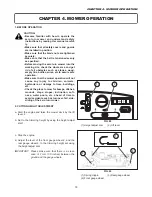
Страница 78: ... or damage to trees buildings etc Check the place to mow for bumps ditches mounds steps slopes inclination soft ness water pools etc ahead of time to avoid accidents such as turnover fall side sliding of the zero turn mower 2 CUTTING HEIGHT ADJUSTMENT a Start the engine and raise the mower deck by the lift lever 2 b Set to the trimming height by using the height adjust dial 1 c Stop the engine d A...

Страница 79: ... control lever gradually to drive the Zero turn mower into the working site CAUTION Before starting to move the zero turn mower be sure to lock the rear gauge wheels either in vertical or slanted positions e Release the drive control lever gradually to stop the zero turn mower f Shift the lift lever to down position d to lower the mower on the ground g Turn the PTO switch 3 to the ON M position IM...

Страница 80: ...ely If not consult your dealers Never attempt to keep on operating the zero turn mower without locating and correcting the cause of trouble When leaving the zero turn mower to remove obsta cles such as twigs pebbles etc the PTO switch must be turned to the OFF N position and the parking brake applied 5 STOPPING MOWING OPERATION a Release the dive control levers and shift to lock position b Shift t...

Страница 81: ...nough for the next finishing pass Then finish to the desired grass height The second travelling pass should be shifted side ways by 20 cm 8 in or so or travel perpendicu lar to the first passes which will result in a beau tiful even finish ii When trying to finish in one pass select a sufficiently slow travelling speed It may also be required to set the cutting width to half or one third of that f...

Страница 82: ...n the left side wall of the gear case b Check to see if a small amount of oil overflows through the plug hole If so the level is normal If not replenish with gear oil SAE80 through the plug hole using an oil pitcher or the like IMPORTANT Before replacing the level plug by sure to wrap the threads with sealing tape without fail or oil may leak through the plug Replacement of oil IMPORTANT Replace o...

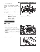
Страница 83: ...rs 2 INSPECTION AND REPLACEMENT OF TIMING BELT Check if belt is tensioned properly When its tension is correct clearance between coils of tension spring should be 0 03 0 04 0 9 1mm or total length of tension spring when installed should be 5 12 130 1mm Inspection of belt a Remove both the belt covers installed on the mower deck b Check the belt for damage and dirt If it is smeared with oil or dirt...

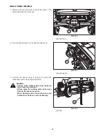
Страница 84: ...Tighten lock nut of tension rod securely to prevent loss of tension Be sure to use the following belt size HOW TO JACK UP a Turn on the engine and raise the mower deck to its maximum b Stop the engine and apply the parking brake c Set the gauge wheel to the minimum trimming posi tion Set the height adjust dial to the maximum trim ming position d Lower the mower deck and remove the lift link pin at...

Страница 85: ...everse to return the respective parts to their original position DANGER Choose a flat stable surface when perform ing the jack up operation Please apply the parking brake before per forming the above procedure When working under the machine the jack handle must he fixed on the handle stay 4 Jack fix pin 5 Jack handle 6 Jack 6 4 5 FIG 100 FIG 101 FIG 102 ZERO TURN MOWER ...

Страница 86: ... IMPORTANT If the blade ends have become round due to wear enlarged clearance between blades leave uncut grass behind The blade should be checked timely and worn ones should be replaced immediately Low cutting height or the operation just after soil has been applied will wear blades rapidly The blades should be checked more frequently a New Blade b Blade with rounded edge c Exessively worm blades ...

Страница 87: ...e wheels and rollers 5 CLEANING OF MOWER DECK a Remove both belt covers and clear the grass and dust accumulated under the cover before operation or shorter service life of the belts and damage to bear ings and oil seals will be caused CAUTION Be sure to replace the removed covers after cleaning b Each blade shaft end and tension pulley end are equipped with a grease fitting Inject grease through ...

Страница 88: ...s very dangerous Besides this will cause noisier operation 7 FILLING DIAGRAM All the shafts mentioned below have a grease fitting on their end Grease them up periodically The gear case should also be serviced periodically for oil replenishment and replacement 1 Mower deck 4 Washer 2 Stopper plate 5 Nut 3 Stopper 6 Discharge cover 1 2 3 5 6 4 4 4 2 3 2 1 2 5 4 4 Ref NO 1 2 3 4 5 Filling points Bebe...

Страница 89: ...e Clean after every 50 h There should be no grass or dust accumulated Belt Clean after every 50 h Criteria for replacement Deep crack over half the thickness of belt Worn out side wall canvas Greasing points Grease up after every 50 h Bolts and nuts There should be no loose ones Pins and clips There should be no lost or deformed ones Inspection replenishment and adjustment Cleaning and washing Rep...

Страница 90: ... remove grass and other objects tangled around pulleys and shaft 7 Check V belt and loosen adjustable tensioner 8 Remove all rust and touch up where paint has peeled off with touch up paint supplied by ISEKI 9 Store mower in a dry place with wooden blocks placed under it and cover with tarpaulin 10 Grease all grease points and check bearings IMPORTANT Insist on ISEKI genuine parts when replacing C...

Страница 91: ... Worn blades Clogged inside of mower deck Improperly adjusted gauge wheels Too tall grass Two blades are not installed on the same level or they are deformed Adjust mower mounting Slow down Replace them with new ones Clean Adjust them properly Mow it in two steps Correct Drive belt is slipping or broken Broken tension spring Too fast travelling speed Too low engine speed Worn or broken blades Blad...

Страница 92: ...Broken gears Re tighten them Clean Replace it with a new one Replace it with a new one Adjust belt tension spring properly Consult your dealer Foreign matter caught in shaft Broken wheel Short of grease Clean Replace it with a new one Inject grease Too low engine speed Too fast travelling speed Foreign matter caught between blade and blade support Foreign matter caught in a pulley Defective engine...

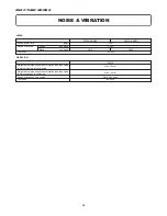
Страница 93: ...ed root mean square acceleration less than value to which the arms are subjected Weighted root mean square acceleration less than value to which the body is subjected Speed of rotation of the engine Test code Speed of rotation Engine min 1 rpm Blade min 1 rpm Test code ISO 5349 EN 836 VIBRATION NOISE VIBRATION ZERO TURN MOWER ...

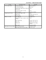
Страница 94: ...95 CHAPTER 7 TROUBLESHOOTING ...

Страница 95: ...96 ZERO TURN MOWER ...

Страница 96: ...SZ330 SSM60 SSM72 Overseas Business Division 5 3 14 Nishi Nippori Arakawa ku Tokyo 116 8541 Japan Phone 03 5604 7658 Fax 03 5604 7703 OM SZ330F EN 10 1005 01 10 Printed in Japan ...

Отзывы: